BBC Microbit
![]()


BBC micro:bit
Unicorn pHAT
Introduction
The Unicorn pHAT is a Raspberry Pi accessory made by the UK electronics company, Pimoroni. The board has 32 SK6218 RGB LEDs arranged in a 4x8 grid. It costs £10. The SK6218 LEDs can be controlled using the Neopixel library.
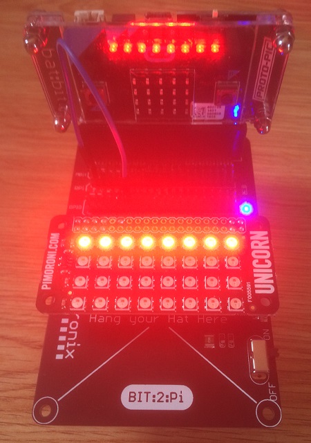
This photograph shows the Unicorn pHAT on a 4tronix Bit:2:Pi. As well as making the connections easier, the Bit:2:Pi provides the power for the pHAT. The photograph is at low low brightness. The first row of 8 pixels is lit. The other red lights are the reflections of these in the Bat:Bit case I was using for the micro:bit. The blue LED is the power indicator for the Bit:2:Pi. This is one of Will's pHATs. Without his collection of Pi accessories and interest in hacking them, I might not have spent so much time with the HATs and pHATs.
Like all Pimoroni products, it's a lovely board to work with. It has a lot of LEDs for the price is astonishingly bright when powered properly. If you have more pHATs and HATs than you can use on your Raspberry Pi collection, this is an excellent board to repurpose for use with the micro:bit. Other than power and ground, you need only one data pin.
The Circuit
In the photograph, you can make out a single blue jumper wire. That is a connection from micro:bit pin0 to GPIO 12 (BCM 18) on the Raspberry Pi. In the photograph, the Bit:2:Pi is providing power from 3xAA batteries in a holder underneath the board.
If you were getting the board to use only with the micro:bit, it would make sense to not solder on a Pi header. Instead, put terminal connectors on 5V and GND pins and headers for the GPIO pin and another ground pin on the board.
If you are hacking this together with jumper wires (good for you), you connect your batteries (3xAA or LIPO) to the 5V pin on the pHAT and one of the GND pins. Jumper a connection to the micro:bit GND from one of the other GND pins on the pHAT. Finally, connect a micro:bit GPIO pin (I used pin 0) to GPIO12 (BCM 18) on the pHAT.
Programming
To begin with, just deal with them like you might a strip of Neopixels. The only addition I've made to code written for other pages is a function to allow you to set a pixel by specifying its xy coordinates in the 4x8 matrix.
from microbit import *
import neopixel

# Initialise neopixels
npix = neopixel.NeoPixel(pin0, 32)

# Define some colours
red = (64,0,0)
green = (0,64,0)
blue = (0,0,64)
nocol = (0,0,0)

# light all neopixels with given colour
def light_all(col):
    for pix in range(0, len(npix)):
        npix[pix] = col
    npix.show()
    return

# wipe a colour across pixels one at a time
def wipe(col, delay):
    for pix in range(0, len(npix)):
        npix[pix] = col
        npix.show()
        sleep(delay)
    return

# set a pixel colour using x,y coordinates
def set_pix(x,y,col):
    npix[y*8+x] = col

# light pixels individually using xy coords
for yy in range(4):
    for xx in range(8):
        set_pix(xx,yy,green)
        npix.show()
        sleep(250)

# turn them off
light_all(nocol)
sleep(500)
# wipe a colour across the pixels
wipe(red,150)
Ideas & Challenges
The pixels update pretty quickly and you don't need a lot of code to make Neopixels work. The grid provides a pretty powerful source of light and works well diffused. This makes a good basis for a mood lamp. My most popular 'mood lamp' at home is a circle of 8 pixels which circulate a rainbow pattern slowly, with some fading in and out. It gets positioned behind some clear glass ornaments and throws out all sorts of patterns as it hits the glass.
There are a fair few other snippets of Neopixel code on this site and many more in the wilds of the WWW. There are even some examples written for the same size matrix. Hunt these down and implement them. Some rainbow action is always nice with the little Neopixels.
The grid is suitable for making indicators for other projects. Use colour inventively and you can make a lovely display for temperature readings. One interesting way to produce colour is with analog readings. That might be from something a user directly controls, like a potentiometer or rotary encoder. More interesting would be to use something that varies more widely in its readings. Analog readings on the micro:bit are 10 bit values (0 to 1023). Converting them to bytes means you divide by 4. That is a right shift of 2 place values in binary. Use that value for one of the colour channels. You have to choose your devices quite carefully for this to work well.
Using only one colour or off for each pixel, you can treat each row of pixels as a byte in binary. Sort out some suitable inputs (8 buttons and a potentiometer/rotary encoder) and you some sort of calculator or utility for working with binary numbers. You will need to use a shift register, multiplexer or a breakout like the MPR121 to get a decent number of inputs.
Implement and extend any of the games that worked on the micro:bit matrix and consider what the extra width or height of the matrix offers, as well as the additional information you can display because of the colours. Perhaps start by navigating a single pixel around the matrix, using the accelerometer or buttons.
Having the choice of colours for each LED means than you can do things like use different colours to represent different objects in a game. This makes things a lot easier than on the micro:bit, where you use blinking and fading to create your user interface. This is easier to code as well as easier to decode for a player. For example, you could use a 3x3 subsection of the grid to represent a Noughts & Crosses board. You could make a Snakes & Ladders game, using different colours to represent the top and bottom of the snakes and ladders, and a colour for each player.