BBC Microbit
![]()


BBC micro:bit
Real Time Clock
Introduction
A real time clock (RTC) allows your micro:bit to know the time. The internal timing of the micro:bit isn't good enough if you need to time something accurately over long periods of time.
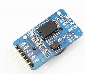
Many of the RTC breakout boards that you can buy online are wired up with 5V logic in mind and won't work with the micro:bit without more tinkering than I am prepared to do. This DS3231 breakout board works comfortably at 3V logic and is easy to interact with. This board cost me under £3 and came with the battery.
Most RTCs communicate using the inter-integrated circuit protocol (i2c). There is a MicroPython library that gives us access to a minimal set of functions for working with i2c.
Circuit
You will need an edge connector breakout to be able to set up this circuit. The i2c protocol is hardware specific and only works on pins 19 and 20. You need a reliable connection and these are small segments on the edge connector.
Look again at the image of the RTC breakout board.
You will need to connect 4 of the pins on the left of the image.
- Connect GND on the breakout to GND on the microbit.
- Connect VCC to 3V.
- Connect SDA to pin 20.
- Connect SCL to pin 19.
Programming - Testing & Setting The Time
The purpose of this program is to set the time and to read from the RTC. Output will be printed and can be viewed in the REPL terminal.
from microbit import *

def bcd2dec(bcd):
    return (((bcd & 0xf0) >> 4) * 10 + (bcd & 0x0f))

def dec2bcd(dec):
    tens, units = divmod(dec, 10)
    return (tens << 4) + units

def get_time():
    i2c.write(addr, b'\x00', repeat=False)
    buf = i2c.read(addr, 7, repeat=False)
    ss = bcd2dec(buf[0])
    mm = bcd2dec(buf[1])
    if buf[2] & 0x40:
        hh = bcd2dec(buf[2] & 0x1f)
        if buf[2] & 0x20:
            hh += 12
    else:
        hh = bcd2dec(buf[2])
    wday = buf[3]
    DD = bcd2dec(buf[4])
    MM = bcd2dec(buf[5] & 0x1f)
    YY = bcd2dec(buf[6])+2000
    print(DD,MM,YY,hh,mm,ss,wday)
    return

def set_time(s,m,h,w,dd,mm,yy):
    t = bytes([s,m,h,w,dd,mm,yy-2000])
    for i in range(0,7):
        i2c.write(addr, bytes([i,dec2bcd(t[i])]), repeat=False)
    return

addr = 0x68
buf = bytearray(7)
#set_time(0,0,12,5,1,4,2016)
sleep(1000)

while True:
    get_time()
    sleep(1000)
If you run this code as it is and look in the REPL terminal, you will see 7 numbers with a space between each one. The first 3 are the day, month and year. Then you get hours, minutes and seconds. Finally you get a number from 1 to 7 representing the day of the week.
If you haven't previously set the time, this will be incorrect. You will see the time change logically though.
If you remove the # from the line that reads #set_time(0,0,12,5,1,4,2016), you can set the time and date. The order of the numbers should be seconds, minutes, hours, week day, day, month, year. You only do this once and then remove the line of code. The battery will keep the time for a few years, even if you don't provide any power to the board.
Programming - Using
Now for a simpler program that uses our time reading to turn the micro:bit into a watch. The two lines that set the variable str_time are not meant to end with line breaks, this is the code box wrapping the text that is too wide.
Press the A button to see the time scroll across the screen, the B button for the date.
from microbit import *

def bcd2dec(bcd):
    return (((bcd & 0xf0) >> 4) * 10 + (bcd & 0x0f))

def dec2bcd(dec):
    tens, units = divmod(dec, 10)
    return (tens << 4) + units

def get_time():
    i2c.write(addr, b'\x00', repeat=False)
    buf = i2c.read(addr, 7, repeat=False)
    ss = bcd2dec(buf[0])
    mm = bcd2dec(buf[1])
    if buf[2] & 0x40:
        hh = bcd2dec(buf[2] & 0x1f)
        if buf[2] & 0x20:
            hh += 12
    else:
        hh = bcd2dec(buf[2])
    wday = buf[3]
    DD = bcd2dec(buf[4])
    MM = bcd2dec(buf[5] & 0x1f)
    YY = bcd2dec(buf[6])+2000
    return [hh,mm,ss,YY,MM,DD,wday]


addr = 0x68
buf = bytearray(7)

while True:
    if button_a.is_pressed():
        tm = get_time()
        str_time = '{0:02d}'.format(tm[0]) + ":" + '{0:02d}'.format(tm[1]) + ":" + '{0:02d}'.format(tm[2])
        display.scroll(str_time)
    elif button_b.is_pressed():
        tm = get_time()
        str_time = '{0:02d}'.format(tm[5]) + "/" + '{0:02d}'.format(tm[4]) + "/" + '{0:04d}'.format(tm[3])
        display.scroll(str_time)
    else:
        display.clear()
Challenges
- The clock could have more features than this. An alarm would be a good thing to have on a watch. Add a buzzer. Store a time you want the alarm to go off. Check every second or half second if the alarm time has been reached. If it has, play an alarm tune a couple of times. You can have the alarm go off until a button is pressed or have it automatically stop after a time.
- Make it so the user can set the time, alarm and date from the micro:bit.
- A time-based animation would be nice.
- Any project needing accurate timing would be possible. A kitchen timer, making the micro:bit do something for a specific period of time and then stopping. Consider what you might do now that you have the time.
- You could make a binary clock display on the micro:bit matrix itself. You would have to think carefully about how you represent the binary values visually on the matrix but it is possible. Some hints are shown below,
We need at least 4 place values for the hour (12hr format), 6 place values for the minutes, and 6 for the seconds. With 16 LEDs, you could do,
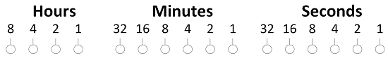
So the following pattern...
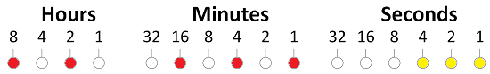
... makes the time, 8+2 = 10 hours, 16 + 4 + 1 = 21 minutes, 4+2+1 = 7 seconds.
The problem is only having 5 LEDS in a row on the matrix. So, how about having the first row for the hours, using two rows each for the minutes and then seconds. You only need one extra place value, so use the leftmost LED of the second and fourth rows of the matrix.
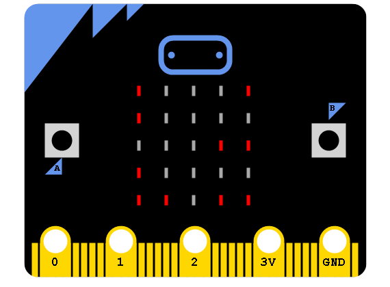
This micro:bit is showing 17:35 and 59 seconds.