BBC Microbit
![]()


BBC micro:bit
Shifting In
Introduction
The CD4021B integrated circuit is an 8 stage static shift register. It converts parallel input into serial. This means that we can connect 8 digital inputs and use 3 pins to read them all.
This gives us a reliable reading for individual buttons and combinations of buttons. I used miniature 2 pin buttons for the circuit in the diagram but you can use ordinary size push buttons as well as 8 pin DIP switches for this.
Circuit
There are a lot of wires here. Take care with this one.
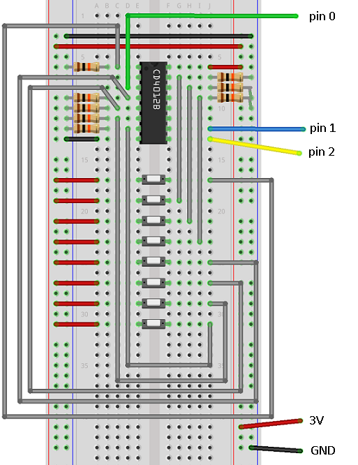
Start with the IC. Here is the pinning diagram to help you,
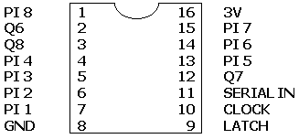
The pins marked PI are parallel inputs. Connect each of these with a resistor to GND. Connect the negative pin of each button to the same rows on the breadboard.
Programming
This is a small Python program to read the button inputs and encode them in a binary string. You need to use the REPL window or a terminal emulator to see the output.
from microbit import *

def shiftIn():
    pin2.write_digital(1)
    sleep(1)
    pin2.write_digital(0)
    bite = 0
    for i in range(7,-1,-1):
        pin1.write_digital(0)
        sleep(1)
        bite = bite + (pin0.read_digital()<<i)
        pin1.write_digital(1)
        sleep(1)
    return bite

while True:
    reading = shiftIn()
    print('{:08b}'.format(reading))
    sleep(20)
The shiftIn function does the work here. The latch pin is switched from high to low to read the parallel inputs. The clock pin is driven low at the start of the loop innards, the data pin is then read. The clock pin is driven high before the next iteration.
The left shift operator is used here to help is create a binary pattern to represent our button states.
Challenges
- This page gets you as far as a byte telling you which buttons are pressed. You need to do some work in the while loop to act upon the readings. A simple starting point would be changing the LED matrix to display a number or pattern of lights.
- 8 buttons is enough to make an 8 key music instrument with a buzzer or some headphones.
- With an edge connector, you could use a shift out register to match up 8 LEDs to the pushbuttons.
- You can chain two or more of these integrated circuits together. The code and circuit used here was based on a description on the ShiftOut page of the Arduino Playground. Search for this and you will be able to find out how to connect another shift register alongside this one.
- An 8 button game sounds like an idea. A binary quiz perhaps, using the LED matrix as a display.