BBC Microbit
![]()


BBC micro:bit
16x2 Serial LCD
Introduction
This page concerns the Sparkfun Serial Enabled 3.3V 16x2 LCD Character Display. It consists of a normal LCD display with a 'backpack' circuit soldered to the controller board. The backpack converts UART into the control signals that the display needs. This means that, other than power and ground, you only need a single data pin on the micro:bit to control the display.
I've had this a while and only just got round to connecting it to the micro:bit. I seem to remember that it was not particularly cheap. It is however, the easiest way to get readable character data from the micro:bit. The display requires no configuration or initialisation beyond waiting for half a second on startup. It is set up to receive character data as bytes over UART, which is what UART is designed to send. This means that you don't need to write a complex driver to make it work.
The simplicity of the interface means that you need far less code in your program than you do for most other displays. This means that you can easily add it onto projects where you want to get some text output and you don't run out of memory.
Circuit
There are only 3 connections to make. Power and Ground connect as you expect. I connected to pin12 to make sure that I left the most useful pins free.
The backpack has terminal blocks. I just screwed in my male male dupont cables with a weeny screwdriver.
Programming
This first program can be used to test that the display is working.
from microbit import *

# blank string to clear LCD
clear = " "*32

# choose cursor position - row 0,1 col, 0-15
def move_cursor(row,col):
    cmd = [254,128]
    if row==1:
        cmd[1]+=64
    cmd[1]+=col
    uart.write(bytes(cmd))
    sleep(10)


# wait half a second for the splash screen
sleep(500)
# initialise uart
uart.init(baudrate=9600, bits=8, parity=None, stop=1, tx=pin12)

# clear display
move_cursor(0,0)
uart.write(clear)
move_cursor(0,0)
uart.write("Hello World!")
sleep(10)

# return the uart to its default state
# will send a character
uart.init(115200)
When you are using UART, error messages and REPL output get sent through your connection. The last line of the program returns the UART to its default state (USB). If you don't do this, the REPL output will fill the display. This can be a little bit confusing at first - foxed me for a while until I realised the characters on the display were what you'd see from the REPL. This meant that the UART connection and baud rate had to be correct or the display would display genuine rubbish.
When the UART is returned to the USB connection, you will have a single character sent to the display. If you don't leave a small delay after the last write to the display before doing this, you will 'lose' a character from the message. Since there is only a single character, the effect is tolerable if you want to do some complicated switching of the UART pins. If you wanted to use the REPL to send commands for the LCD, it would be just about possible. If you always make sure the cursor is ready to put the extra character in the same unobtrusive spot.
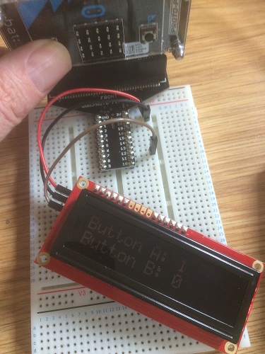
Watch out for trying this on batteries. In the photograph, I'm using a portable USB battery. When my battery solution was 3V max, the display wasn't so happy. As the batteries drain they give a little less voltage and the lighting was a bit pants.
More often than not in a project, you have an infinite loop. When your program is working normally, there is no leakage of REPL or error messages to the display. In the following example, the display is used to monitor the state of the micro:bit buttons.
from microbit import *

# blank string to clear LCD
clear = " "*32

# choose cursor position - row 0,1 col, 0-15
def move_cursor(row,col):
    cmd = [254,128]
    if row==1:
        cmd[1]+=64
    cmd[1]+=col
    uart.write(bytes(cmd))
    sleep(10)


# wait half a second for the splash screen
sleep(500)
# initialise uart
uart.init(baudrate=9600, bits=8, parity=None, stop=1, tx=pin12)

# clear display
move_cursor(0,0)
uart.write(clear)
move_cursor(0,0)
uart.write("Button A: ")
move_cursor(1,0)
uart.write("Button B: ")
while True:
    move_cursor(0,10)
    if button_a.is_pressed():
        uart.write("1")
    else:
        uart.write("0")
    move_cursor(1,10)
    if button_b.is_pressed():
        uart.write("1")
    else:
        uart.write("0")
    # always try to spare some time with serial
    sleep(10)
The first thing to note here is that we move the cursor to the position that we want to write. If we were doing this with a pixel-based display, we'd be managing a large buffer and writing the whole thing each time. By only writing to the spaces that we need to, we can minimise flicker on the display and push the connection a little harder.
It's always worth leaving a small delay in programs using UART in a loop like this. In this case, we are writing data and it's less of an issue. When you are reading data from UART, leaving out the delays can lead to more data being read from the connection than can be processed. A few milliseconds is often the difference between workable and unworkable.
What Next?
The first thing that you might want to do is to read Sparkfun's QuickStart guide on the board. It gives a little more explanation and will certainly help you to understand what I've done in the move_cursor function. There are also some links to the other things you can do, like change the baud rate of the connection, fiddle with the backlight settings and define characters.
If you are mainly drawn by how easy it is control the display, start by getting some analog readings from sensors on the display, or using it to show the score for a game. That will help you get used to managing timing in your code and updating the display to avoid flicker.
With the right kind of inputs, you can use the display as a user interface for your project. Since you are only using one data pin, there's a lot of scope for your inputs. The micro:bit buttons alone are sufficient for basic input but laborious for a user doing more than a couple of settings. A rotary encoder is a good replacement for multiple button presses in an interface. Combine it with a button press to scroll nicely through menu options before choosing something.
If I hacked together all of the different button and button-like inputs I could fit on the remaining pins, leaving out the USB keyboard but using shift registers, port expanders and multiplexers, I think I've got enough for a scientific or programmer calculator for the display. An integer calculator that allowed input and showed output in different number bases (binary, octal, denary, hexadecimal) would be a nice project. You could add buttons that let you do some nice bitwise functions too.