BBC Microbit
![]()


BBC micro:bit
MCP23017 Port Expander
Introduction
The MCP23017 is an integrated circuit which provides 16 digital GPIO connections that can be accessed over I2C. There is also an SPI version of the same chip. It can work at the same voltage as the micro:bit is fairly easy to connect in a circuit. It is not particularly difficult to program.
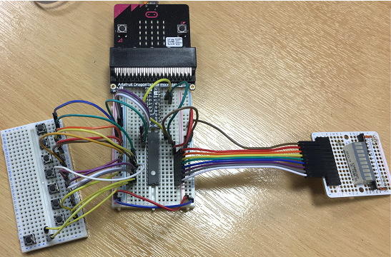
The image shows 8 buttons connected to portA of the integrated circuit and 8 LEDs connected to portB. The bar graph on the right hand side of the image is soldered to an Adafruit perma-proto board with some females headers and a resistor network.
The Circuit
The following pinout image comes from the datasheet for the MCP23017.
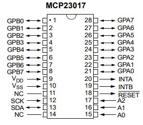
In the pinout, the pins labelled GPA and GPB are the GPIO pins. There are two 'ports', A and B. When programming, you access the pins of a port for reading or writing at the same time. If you had 8 inputs and 8 outputs (like my test circuit in the first image of this page), it's easier to connect all of the inputs to one port and all of the outputs to the other port. This isn't absolutely necessary though.
You need to connect the SCL and SDA pins (the I2C pins) to pin 19 and pin 20 on the micro:bit. These are the only pins you need to use on the micro:bit (other than power) to control those 16v extra connections.
The VDD pin is for your 3V connection. The VSS pin is for GND. Additionally, you will need to connect the A0,A1 and A2 pins somehow. These are used to set the I2C address for the chip. If you are only using one of the chips, connect all of these to GND and the address will be 0x20. Finally, you will need to connect the RESET pin to 3V.
In my test circuit image at the top of the page, I have the buttons connected to port A and the LEDs of the bar graph connected to port B. The integrated circuit is rotated 180° from the pinout image. I wanted each button press to be able to activate a corresponding LED.
Programming
For my test program, I wanted to check that I could read from and write to the GPIO. I wrote a basic class for doing that,
from microbit import *

class mcp23017:
    def __init__(self, a = 0x20):
        self.ADD = a

    # BANK A=0 B=1
    def set_dir(self,bank,direction):
        data = bytes([bank,direction])
        i2c.write(self.ADD, data)

    def set_pull(self,bank,pull):
        data = bytes([bank + 0x0c,pull])
        i2c.write(self.ADD,data)

    def dig_write(self,bank,value):
        data = bytes([bank + 0x12,value])
        i2c.write(self.ADD,data)

    def dig_read(self,bank):
        buf = bytes([bank + 0x12])
        i2c.write(self.ADD,buf)
        return i2c.read(self.ADD,1)[0]

# test
p = mcp23017()
# set bank A to inputs
p.set_dir(0,0xff)
# set bank A to pullup
p.set_pull(0,0xff)
# set bank B to outputs
p.set_dir(1,0)
# turn bank B off
p.dig_write(1,0)

# test the leds
for i in range(8):
    p.dig_write(1,2**i)
    sleep(500)

# loop for reading buttons
while True:
    btns = p.dig_read(0)
    p.dig_write(1,btns^0xff)
    sleep(20)
There are a number of registers, each one storing a byte, that are used to work with the MCP23017.
0x00, 0x01 These registers are used to set the direction (input or output) of the pins.
0x12, 0x13 Read from these registers or write to them for input and output.
0x0c, 0x0d These registers are used to enable internal pull-up resistors when using switches.
When you use pull-up resistors, you get a reading of 0 when the button is pressed, otherwise you get a 1.
Simon Game
When I first wrote the Simon game for the micro:bit, it took up 9 GPIO pins. I wanted to see how easy it would be to have it use only the two I2C pins, leaving opportunities for me to add other features to the circuit.
I connected the buttons to port A and the LEDs (with a resistor for each one) to port B. I connected a buzzer to pin 2 and got something looking like this,
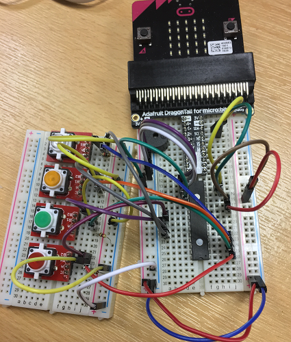
I had to make some adaptations to the program to account for the port expander. I added a utility method to the class to read the button inputs as a list, first inverting the bits. This helps to see if only 1 button is being pressed when you take the reading. Other than that, the program is based on the one I originally wrote.
from microbit import *
import music
import random


notes = [659, 880, 330, 554]

class mcp23017:
    def __init__(self, a = 0x20):
        self.ADD = a

    # BANK A=0 B=1
    def set_dir(self,bank,direction):
        data = bytes([bank,direction])
        i2c.write(self.ADD, data)

    def set_pull(self,bank,pull):
        data = bytes([bank + 0x0c,pull])
        i2c.write(self.ADD,data)

    def dig_write(self,bank,value):
        data = bytes([bank + 0x12,value])
        i2c.write(self.ADD,data)

    def dig_read(self,bank):
        buf = bytes([bank + 0x12])
        i2c.write(self.ADD,buf)
        return i2c.read(self.ADD,1)[0]

    def btn_list(self,bank):
        reading = self.dig_read(bank)
        reading ^= 0xff
        result = [reading >> i & 1 for i in range(7,-1,-1)]
        result.reverse()
        return result

def GetRandomSequence():
    return [int(4*random.random()) for i in range(0,100)]

def Win(mcp):
    for i in range(0,4):
        mcp.dig_write(1,0x0f)
        for j in range(0,4):
            music.pitch(notes[j],-1, pin2)
            sleep(50)
        mcp.dig_write(1,0)
        sleep(50)
    music.stop(pin2)
    sleep(1000)

def Loss():
    music.pitch(131,500,pin2)
    sleep(1500)

def PlaySequence(t, s, mcp):
    for i in range(0,t):
        mcp.dig_write(1,2**s[i])
        music.pitch(notes[s[i]],500,pin2)
        mcp.dig_write(1,0)
        sleep(200)

def PlayGame(mcp):
    turn = 0
    sequence = GetRandomSequence()
    userSequence = [0]*100
    seqlen = 0
    playing = True
    played = False
    while playing==True:
        if turn==0:
            # Just started
            Win(mcp)
            turn = turn + 1
        if seqlen==0 and played==False:
            # Sequence needs playing
            PlaySequence(turn, sequence,mcp)
            played = True
        elif seqlen==turn:
            # User has entered the sequence
            Win(mcp)
            played = False
            turn = turn + 1
            seqlen = 0
        else:
            # User still entering pattern
            btns = mcp.btn_list(0)[:4]
            if sum(btns)==1:
                userSequence[seqlen] = btns.index(1)
                if userSequence[seqlen]!=sequence[seqlen]:
                    Loss()
                    playing = False
                else:
                    mcp.dig_write(1,2**userSequence[seqlen])
                    music.pitch(notes[userSequence[seqlen]],500,pin2)
                    mcp.dig_write(1,0)
                    seqlen = seqlen + 1
p = mcp23017()

# set bank A to inputs
p.set_dir(0,0x0f)
# set bank A to pullup
p.set_pull(0,0x0f)
# set bank B to outputs
p.set_dir(1,0)
# turn bank B off
p.dig_write(1,0)

while True:
    display.show(Image.ARROW_W)
    if button_a.was_pressed():
        display.clear()
        PlayGame(p)
        sleep(1000)
    sleep(50)
Review
I'll definitely be reaching for this integrated circuit whenever I am running out of GPIO or working with a component that consumes more pins than I would like. When working with a lot of buttons, it's convenient to read a single byte to get the button states. The other bonus is that the IC costs just over £1 to buy.