BBC Microbit
![]()


BBC micro:bit
16x2 Character LCD Display
Introduction
LCD character displays are a useful way to get output from a microcontroller. The one used on this page is a fairly standard size, able to display 2 rows of 16 characters. The advantage we have over the LED matrix is that we don't need to have our text scrolling across the screen. This allows us to display things like sensor readings so that we can see them change in real time.
The most common standard for the controllers built into these displays is the Hitachi HD44780 LCD controller protocol. This is a parallel interface (we need to send signals down several wires at the same time). For many microcontrollers that have been around longer than the micro:bit (like Arduino), there are libraries to help you interact with common hardware like this. Although no such libraries exist for the micro:bit, I have been able to make a rough conversion of the Arduino library code for use with the micro:bit.
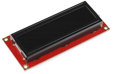
The LCD display that I am using is the Sparkfun 3.3V Basic 16x2 Character LCD Display. It looks like this,
Circuit
The HD44780 LCD controller interface is made up of 16 connections, not all of which are needed to communicate with the display. On most modules, these are broken out to 0.1 inch spaced pins and are in the following order,
| Pin | Name | Purpose |
|---|---|---|
| 1 | VSS | Ground |
| 2 | VDD | 3.3V Power |
| 3 | VO | Contrast Adjustment |
| 4 | RS | Register Select |
| 5 | RW | Read/Write |
| 6 | CLOCK | Enable |
| 7 | D0 | Bit 0 |
| 8 | D1 | Bit 1 |
| 9 | D2 | Bit 2 |
| 10 | D3 | Bit 3 |
| 11 | D4 | Bit 4 |
| 12 | D5 | Bit 5 |
| 13 | D6 | Bit 6 |
| 14 | D7 | Bit 7 |
| 15 | A | Backlight Anode (+) |
| 16 | C | Backlight Cathode (-) |
We will need to connect up LCD pins 1 & 2 to our power pins on the micro:bit as well as connecting LCD pins 15 & 16 up to the power to make the backlight work. The resistor for this light is built into the display module.
The VO pin is needed and is best connected using a variable resistor (potentiometer) so that the contrast can be adjusted easily.
The RS pin needs to connect to a GPIO pin. It is set to LOW when we send commands to the display (like clearing the screen or moving the cursor) and set to 1 when we are sending character data.
The RW pin is set to LOW when writing to the LCD and set to HIGH when reading. We don't need to read from the display so we can save ourselves a GPIO pin by connecting this pin directly to GND.
The CLOCK or ENABLE pin must be connected to a GPIO pin. We pulse this pin when we send commands or data to the display.
There are 8 data pins. We can operate the display in either 8 bit or 4 bit mode. 4 bit mode means 4 rather than 8 connections. When we use 4 bit mode, we only connect up D4 - D7 to our GPIO pins. This does mean that we will be sending our bytes in two parts and will be a little slower when updating the display but will save us 4 GPIO connections.
Here it is on a breadboard,
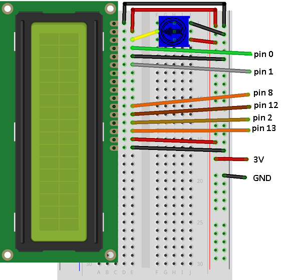
The potentiometer is a 10K Ohm linear potentiometer. 10K or 20K is recommended on the datasheet for these displays.
Programming
The micro:bit hasn't been around long enough for there to be many examples of how to connect to these or any hardware libraries that provide simple functions for you to use. This has been converted from the open source Arduino library with the timings for delays rounded up. This makes the communication a little slower than can be achieved but more than good enough for most uses you want to make of the LCD.
I have left in most of the constants from the library. If you explore a little, you will be able to use these to make use of more of the built-in functionality of the display (like blinking and scrolling text).
from microbit import *

# pin connections
rs = pin0
enable = pin1
datapins = [pin8, pin12, pin2, pin13]

# commands
LCD_CLEARDISPLAY = 0x01
LCD_RETURNHOME = 0x02
LCD_ENTRYMODESET = 0x04
LCD_DISPLAYCONTROL = 0x08
LCD_CURSORSHIFT = 0x10
LCD_FUNCTIONSET = 0x20
LCD_SETCGRAMADDR = 0x40
LCD_SETDDRAMADDR = 0x80

# flags for display entry mode
LCD_ENTRYRIGHT = 0x00
LCD_ENTRYLEFT = 0x02
LCD_ENTRYSHIFTINCREMENT = 0x01
LCD_ENTRYSHIFTDECREMENT = 0x00

# flags for display on/off control
LCD_DISPLAYON = 0x04
LCD_DISPLAYOFF = 0x00
LCD_CURSORON = 0x02
LCD_CURSOROFF = 0x00
LCD_BLINKON = 0x01
LCD_BLINKOFF = 0x00

# flags for display/cursor shift
LCD_DISPLAYMOVE = 0x08
LCD_CURSORMOVE = 0x00
LCD_MOVERIGHT = 0x04
LCD_MOVELEFT = 0x00

# flags for function set
LCD_8BITMODE = 0x10
LCD_4BITMODE = 0x00
LCD_2LINE = 0x08
LCD_1LINE = 0x00
LCD_5x10DOTS = 0x04
LCD_5x8DOTS = 0x00


def InitDisplay():
    # at least 50ms after power on
    sleep(50)
    # send rs, enable low - rw is tied to GND
    rs.write_digital(0)
    enable.write_digital(0)
    write4bits(0x03)
    sleep(5)
    write4bits(0x03)
    sleep(5)
    write4bits(0x03)
    sleep(2)
    write4bits(0x02)
    send(LCD_FUNCTIONSET | 0x08, 0)
    sleep(5)
    send(LCD_FUNCTIONSET | 0x08, 0)
    sleep(2)
    send(LCD_FUNCTIONSET | 0x08, 0)
    sleep(2)
    send(LCD_FUNCTIONSET | 0x08, 0)
    sleep(2)
    send(LCD_DISPLAYCONTROL | LCD_DISPLAYON | LCD_CURSOROFF | LCD_BLINKOFF,0)
    clear()
    send(LCD_ENTRYMODESET | LCD_ENTRYLEFT | LCD_ENTRYSHIFTDECREMENT,0)

# high level commands
def clear():
    send(LCD_CLEARDISPLAY,0)
    sleep(2)

def home():
    send(LCD_RETURNHOME,0)
    sleep(2)

def setCursor(col, row):
    orpart = col
    if row>0:
        orpart = orpart + 0x40
    send(LCD_SETDDRAMADDR | orpart, 0)

def showText(t):
    for c in t:
        send(ord(c), 1)

# mid and low level commands
def send(value, mode):
    rs.write_digital(mode)
    write4bits(value>>4)
    write4bits(value)

def pulseEnable():
    enable.write_digital(0)
    sleep(1)
    enable.write_digital(1)
    sleep(1)
    enable.write_digital(0)
    sleep(1)

def write4bits(value):
    for i in range(0,4):
        datapins[i].write_digital((value>>i) & 0x01)
    pulseEnable()

# Test
InitDisplay()
showText("Hello")
setCursor(0,1)
showText("World")
sleep(5000)
clear()
showText("How are you?")
The little section at the end is the most important for you. The 4 'high level' functions are the ones that you will use to interact with the display after you have called the InitDisplay() function once at the start of your program. Some parts of the Arduino library send the same command several times - I have copied the approach taken there and things work - that was enough for me.
Challenges
- Output hardware like this can be put to many uses. Anything that you display by scrolling across the LEDs will be easier to read on this display. That might be the score for a game or the reading you are getting from a sensor connected on a GPIO pin.
- Use the display to make a stopwatch. Use running_time rather than delays to control your timings and think carefully about how often you update the display.