BBC Microbit
![]()


BBC micro:bit
Sparkfun moto:bit
Introduction
The moto:bit is a motor controller board designed for the micro:bit by the company Sparkun. It has an edge connector, headers for 2 DC motors, a barrel jack power connector and some GPIO headers. It looks like this,
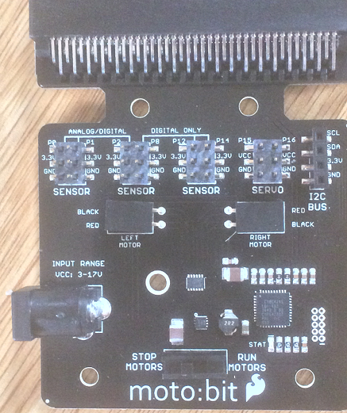
The motor is controlled by i2c, leaving your PWM pins free to use for accessories. The headers have power pins, with two of them having the battery power. There is also a switch to turn the motor power on and off. This only disables the motors and still leaves the micro:bit powered, so a separate switch is needed on the power supply of a portable project.
Programming - Motor Control
A PXT library is available but the board does work well in MicroPython. The commands to control the motors are pretty simple to work out from the Sparkfun library and replicate in MicroPython. There is a facility to invert the motors which is not implemented here - I just swap the motor wires until I have things right. I did add a method to set both motors in a single statement.
from microbit import *

class motobit:
    moto_l = 0x21
    moto_r = 0x20
    moto_on = 0x70

    def __init__(self, address = 0x59):
        self.ADDR = address

    def write16(self,a,b):
        i2c.write(self.ADDR, bytes([a,b]), repeat=False)

    # True or False
    def enable(self, pwr):
        if pwr:
            self.write16(0x70,1)
        else:
            self.write16(0x70,0)

    # 0 for right, 1 for left, speed -127 to 127
    def set_speed(self, motor, speed):
        motor = motor + 32
        if speed>=0:
            self.write16(motor,128 + speed)
        else:
            speed = speed + 127
            self.write16(motor, speed)
    # left and right speeds
    def drive(self,left,right):
        self.set_speed(0,right)
        self.set_speed(1,left)


car = motobit()
car.enable(True)
sleep(5000)
car.drive(127,127)
sleep(1000)
car.drive(-127,-127)
sleep(1000)
car.drive(127,0)
sleep(1000)
car.drive(0,-127)
sleep(1000)
car.drive(0,0)
display.show(Image.HAPPY)
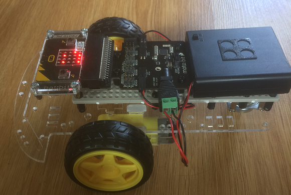
You are going to get an i2c error on the micro:bit when it is not connected to the moto:bit. I also get an error when I first switch on power to the moto:bit and the micro:bit is otherwise unpowered. Reset the micro:bit and it should work. The image below is of my test rig showing a happy face having moved as expected. I used a board and a truckload of standoffs to make up for the awkward mounting on this chassis. When making something more permanent, I glue or epoxy the standoffs to the chassis top. I used a terminal block to DC jack adapter to give me a main power switch.
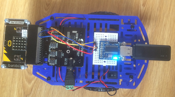
I then mounted the moto:bit on a chassis with better mounting options. On this chassis, the batteries are sandwiched between the two layers. This prevents access to a switch on the battery holder. I snipped up the power cable on a switchless battery holder and put in a rocker switch for main power control.
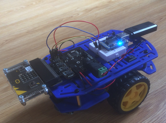
The device on the mini breadboard is a USB host board with a receiver for a third party PS3 controller. This connects via the i2c pins that are broken out on the moto:bit. The car travels in the direction of the dongle. This means that I have the micro:bit mounted the wrong way around and the motors are connected to the opposite pins. This was how I wanted to mount it. For this application, it only affects the speed values used for driving.
My test code for driving the robot with motor control is below and an explanation follows.
from microbit import *

class ps3:

    def __init__(self):
        self.addr = 41
        self.led_cmd = 51
        # initialisation sequence?
        sleep(500)
        self.ps3_led(0x01)
        sleep(500)
        self.ps3_led(0x02)
        sleep(500)
        self.ps3_led(0x04)
        sleep(500)
        self.ps3_led(0x08)
        sleep(500)
        self.ps3_led(0x01)
        sleep(500)

    # 4 bit number, 0 - 3 bits for LEDs 1 - 4
    def ps3_led(self,a):
        i2c.write(self.addr, bytes([self.led_cmd,a]), repeat=False)

    def readall(self):
        i2c.write(self.addr, b'\x00', repeat=False)
        sleep(1)
        buf = i2c.read(self.addr, 32, repeat=False)
        return buf

    def ps3_dpad(self):
        buf = self.readall()
        # left, down, right, up in 4 bits
        return (buf[18]<<3) + (buf[19]<<2) + (buf[20]<<1) + buf[21]

class vroom:
    moto_l = 0x21
    moto_r = 0x20
    moto_on = 0x70

    def __init__(self, address = 0x59):
        self.ADDR = address

    def write16(self,a,b):
        i2c.write(self.ADDR, bytes([a,b]), repeat=False)

    # True or False
    def enable(self, pwr):
        if pwr:
            self.write16(0x70,1)
        else:
            self.write16(0x70,0)

    # 0 for right, 1 for left, speed -127 to 127
    def set_speed(self, motor, speed):
        motor = motor + 32
        if speed>=0:
            self.write16(motor,128 + speed)
        else:
            speed = speed + 127
            self.write16(motor, speed)
    # left and right speeds
    def drive(self,left,right):
        self.set_speed(0,right)
        self.set_speed(1,left)


car = vroom()
car.enable(True)
joy = ps3()
last = 0

spds = [(0,0),(127,127),(31,127),(63,127),(-127,-127),(0,0),(-31,-127),(0,0),
        (127,31),(127,63),(0,0),(0,0),(-127,-31),(0,0),(0,0),(0,0)]

while True:
    d = joy.ps3_dpad()
    if d!=last:
        l,r = spds[d]
        car.drive(l,r)
    last = d
    sleep(10)
I chose to use the 4 D-pad buttons. On this pad, you can only press a maximum of two buttons simultaneously, giving 8 inputs. I chose to use UP and DOWN for forwards and reverse. LEFT and RIGHT, by themselves, do a hard turn forwards. Pressing UP and RIGHT does a less sharp turn to the right.
After copying the D-pad sample code from the page on this site, I modified the ps3_pad method to return a 4 bit integer representing the states of the buttons.
The variable last is used to follow the reading so that we can send messages to the motor controller only when there is a change of state.
The variable spds is a list of tuples of the speeds that correspond to the readings we get from the button and the directions I wanted my vehicle to go for each combination of presses.
The main loop starts by reading the pad. If there is a change of state, the relevant speed is set by picking the values for the motors out of the spds list.
This setup gave a vehicle that was easy enough to drive. There is always a little bit of drift with these types of vehicles, the motors are not absolutely identical in their output and the surface you drive on might make a difference. You can adjust for this in code. If it's not too much, I find that, if you have reasonable remote control of the vehicle, it drives quite nicely without too much fuss.
All in all, the platform is pretty tidy and, on the right chassis, gives you plenty of room for the electronics you can connect to the GPIO. Since the PS3 example uses i2c, there are still 8 GPIO left for doing cool stuff.
Challenges
A few ideas below. Although you do lose some pins that could have been broken out, you do keep your analog/PWM pins and have easy access to the i2c pins. This is where you might look for the possiblities that this board offers. Don't get stuck on the idea that this has to be a vehicle. You might have other ideas that involve motors, servos and sensors.
- Second micro:bit - radio control - with/without external components (nunchuck/SNES?). There is example code for this in the bit:bot pages on this site. It would be fun to make a touch-based input for the motor control, maybe dance mat style. With decent length croc-clip/banana cables, you can do this using the built-in touch inputs. You only have 3 inputs here, but could make it possible to travel in one direction. Arrange the footpads like this,
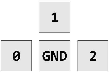
The driver places one leg on the GND pad and steps on one of the others to drive. If you use a CAP1188 or MPR121 breakout, you could have more touch inputs. - You have plenty of GPIO for line sensing.
- A car needs a horn. Some simple work with the buzzer and you're there. You could also go with a speaker and have a talking car.
- Your best bet for some LED decorations would be something like neopixels or a Blinkt, where you don't use up too much of your GPIO. Under-carriage lighting looks pretty good if your chassis has space.
- I used the display for debugging when testing out my code. You could make much better use of it.
- PIR for movement activated robot. This is good for scaring people. If you can't get your speech sounding loudly enough, the moving motors provide a nice shock factor.
- Light sensor and light following. You can get the robot to respond to changes in light by doing something interesting or have it follow the light.
- RTC for robot alarm clock. This might not be for a car, maybe something else being driven by the motors.