BBC Microbit
![]()


BBC micro:bit
PCF8574A Port Expander
Introduction
The PCF8574A is 16-pin integrated circuit. You connect to it using the I2C protocol and it provides 8 input/output pins that can be used for a variety of devices.
You might just be able to make out the integrated circuit in this photo of my test circuit (4 LED buttons).
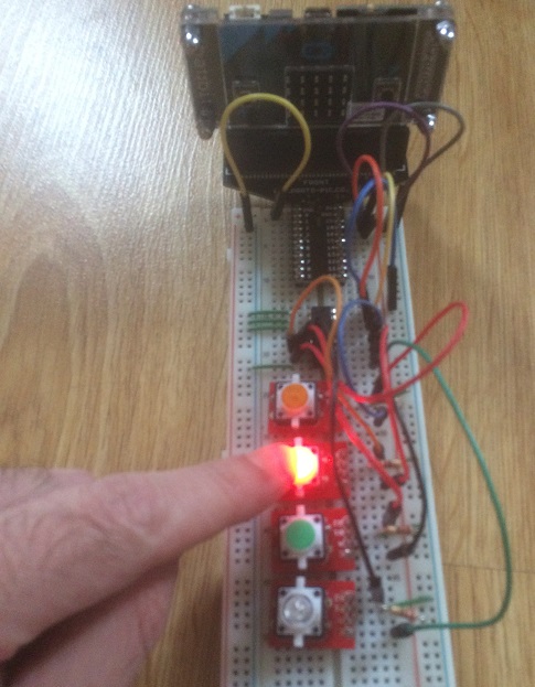
The chip costs a couple of quid to buy and is incredibly easy to use.
The Test Circuit
This is the pinnout from the datasheet for the chip.
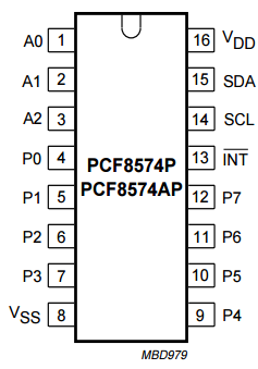
The pins labelled A0 - A2 are used for setting the i2c address. It will be 0x38 if we pull them to GND, read the datasheet to change the address if you have something else on the i2c bus.
The P pins are our GPIO. SDA and SCL are our i2c pins. VDD is power and VSS is GND.
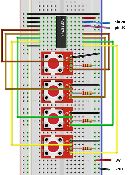
I have shown the LED button breakouts that I used in the diagram. It was a bit easier to make out the principles behind the connections using these. The connections are the same if you do separate buttons and LEDs, as long as you work on a pin-by-pin basis. The buttons are connected from P4 to P7 and the LEDs from P0 to P3. I made the order the same for my inputs and outputs.
The C pin on the LED button breakout is the cathode (negative pin) of the LED. A is the anode (positive pin). The anodes are connected to the power supply via resistors. The cathodes are connected to the P pins on the integrated circuit. This is because the chip cannot source the current needed to drive the LEDs. It can sink the current we need to ground the LEDs from our supply though. The B pins on the breakouts are for the buttons. One of these goes to GND, the other to the P pins on the chip.
Programming
Although you could write a set of helper functions for the chip, it's better to save a little space and write the stuff you need for each scenario.
Output
We can send or read a byte to the chip. The byte that we write represents the states of the 8 pins. It's worth messing around with the REPL to get used to how you work with the chip. I've shown here how to turn an individual pin on or off and how to toggle pins. Change the numbers and you can see how it works. My LEDs are connected to pins 4 - 7.
from microbit import *

# drive pins 4 - 7 LOW (LEDs on)
i2c.write(0x38,b'\x00')
sleep(1500)
# drive pins 4 - 7 HIGH (LEDS off)
i2c.write(0x38,b'\xf0')
sleep(500)

# bytearray of pin states
myio = bytearray([0xff])
# turn P4 LOW - leaving others unchanged
myio[0] &= ~(1<<4)
i2c.write(0x38,myio)
sleep(1000)
# turn P4 HIGH - leaving others unchanged
myio[0] |= 1<<4
i2c.write(0x38,myio)
sleep(1000)

for i in range(10):
    # flip P6
    myio[0] ^= 1<<6
    i2c.write(0x38,myio)
    sleep(1000)

# P4-P7 LOW, one at a time
for i in range(4,8):
    myio[0] &= ~(1<<i)
    i2c.write(0x38,myio)
    sleep(1000)

# off in reverse order
for i in range(7,3,-1):
    myio[0] |= 1<<i
    i2c.write(0x38,myio)
    sleep(1000)
Input
Input might seem a little strange if you are not used to microcontrollers. You put the pins into 'input mode' by making sure you write a HIGH to them. When you read from the chip, your input devices bring the pin low when they are closed. The if statement in the loop checks if a pin is low and turns a pixel on the matrix on to show that. A binary string is also printed to the serial port.
from microbit import *

i2c.write(0x38,b'\xff')
while True:
    # read the pin states as a byte
    a = i2c.read(0x38,1)[0]
    # output to terminal in binary
    print('{:08b}'.format(a))
    for i in range(4):
        if (a>>i)&1==0:
            display.set_pixel(i,0,9)
        else:
            display.set_pixel(i,0,0)
    sleep(10)
Input & Output
This example combines input and output in one program. The relevant LED is lit when its button is held down. The pin states are represented in a binary number, each pin being a place value. If you have the LEDs and buttons paired 0-4, 1-5, 2-6, 3-7, you can do a logical bit shift to make the put the value you read from the LEDs into the positions for the output pins. The 15 that is added is binary 1111, writing the input pins high again.
from microbit import *

myio = bytearray([0xff])
# all high - LEDs off, button pins to input
i2c.write(0x38,myio)

while True:
    # read the pin states as a byte
    a = i2c.read(0x38,1)[0]
    # output to terminal in binary
    print('{:08b}'.format(a))
    # shift reading 4 to left and add 15
    myio[0] = (a<<4)+15
    i2c.write(0x38,myio)
    sleep(10)
Challenges & Ideas
Once you have managed input, output and combinations thereof, it's worth seeing where you might use this in an old project to provide additional GPIO. The Simon project is a nice example of where the GPIO limits of the micro:bit are stretched. Shifting it to the i2c pins could let you do something funky with a display or some LEDs that need the SPI pins.
One of the frustrations of the micro:bit is the default pull of the pins. When you connect up your buttons on the micro:bit, the pin will read low until you close the switch to get a high. In order for this to happen, an internal resistor connects the digital pin to ground. This makes the pin read low until a button is pressed. It is a little more common to use a pullup resistor, though and there are some situations where it kit doesn't work very nicely with the default pulldown. For example, connecting rotary encoders via this chip worked as I wanted, something which I only got going previously by using the pulled-up button pins.
There are clearly scenarios where the chip is likely to be more useful than a shift register, not least because of the reduced number of pins and easier code. It's also going to be useful where you need a load of extra input and a couple of extra outputs, or want to have some LEDs tracking your inputs. A simple D pad and a couple of buttons or LED indicators would be a nice project to use with this.
There are quite a few components and breakouts that need you to drive pins high and low in specific sequences to create the effects that you want. Protocols. There are also circuits, combinations of components that you might use to carry out a specific function. Consider where you could use this chip to control your circuit and make it a part of something a little bigger.
Programming complex circuits with this chip can be a little daunting. Each time you write a byte to set the pin states, you have to remember that you are setting them all. For some situations, this just makes things convenient. In other cases though, the sequence might matter. For example, you might need to clock in data. That normally means putting a clock pin into a specific state, setting your data pins to their correct values, then setting the clock pin to another state. You might even need to pulse the clock pin. Depending on the delays that the component expects, if any, the number of times you write bytes to the PCF8574 might vary a lot from the original, multi-pin program. You may be able to collapse some of your writes, depending on the timings. You may also have to make your program remember the settings for the pins it doesn't want to change. Experiment, see what works and doesn't and try to work out why. That's what it's all about.