BBC Microbit
![]()


BBC micro:bit
Scroll:bit Clock
Introduction
This was the first project I knocked up with the Pimoroni Scroll:bit. I like to make clocks with matrix displays. If I can find a way to display the time nicely, I know that the display is usable for displaying other things, like analog readings. It is the same LED layout and IS31FL3731 driver chip that is found on the Scroll pHAT HD but with an edge connector instead of a Pi GPIO header. There are libraries for MakeCode and MicroPython available from Pimoroni which can be used to do all sorts of cool things with the matrix. You can also write your own code to use the matrix. It costs £13.50. The charlieplexing of the LEDs means that it doesn't draw much power in use but still dazzles. The 119 pixels are in an 11x7 grid which is enough to make readable text, a decent-sized grid game, display a sensor reading, do animations etc. It's a really classy accessory.
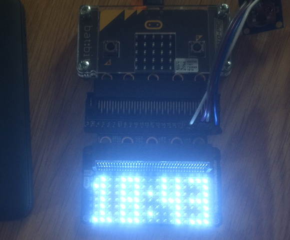
In this project, I used the scroll:bit with a 4tronix Inline Breakout, a handy product that gives access to the micro:bit pins whilst giving you another edge to plug into the accessory. I connected a Hobbytronics DS1338 RTC (which works at 3V) to the I2C pins to read the time. I made a minor adjustment to code I'd previously written and, before I knew it, I had a working clock.
Programming
This is the very simple 3x7 font that I've used in the past. You can fit 4 digits and a colon across the scroll:bit using these digits. It's also enough for displaying analog or accelerometer readings.
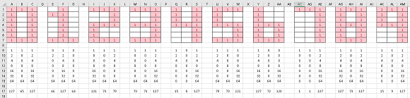
The font is embedded in the code in the list called ds. The numbers are worked out from the binary patterns formed by the red and white cells in the columns. The pixels are turned on one at a time when the display is updated with no buffering. The display only updates when one of the 4 digits of the time needs to change but checks for this once a second.
from microbit import *

class Matrix:
    def __init__(self):
        self.wreg(0x0A,0,1)
        self.wreg(0x0A,1,1)
        self.wreg(0,0,1)
        self.wreg(1,0,1)
        self.fill(0)
        for f in range(8):
            for i in range(18):
                self.wreg(i,0xff)
        self.wreg(0x06,0,1)

    def wreg(self,r,v,c=0):
        if c:
            i2c.write(0x74, b'\xFD\x0B')
        else:
            i2c.write(0x74, b'\xFD\x00')
        i2c.write(0x74, bytes([r,v]))

    def fill(self, value):
        i2c.write(0x74, b'\xFD\x00')
        for i in range(6):
            d = bytearray([0x24 + i * 24]) + bytearray(([value]*24))
            i2c.write(0x74, d, repeat=False)

    def set_xy(self,x,y,b):
        y = 6 - y
        if x > 8:
            x = x - 8
            y = 6 - (y + 8)
        else:
            x = 8 - x
        led = x * 16 + y
        self.wreg(0x24+led,b)

    def set_led(self,led,b):
        self.set_xy(led%17,led//17,b)

    def set_dig(self,c,d):
        x = [0,4,10,14][c]
        ds = [127,65,127,66,127,64,121,73,79,73,73,127,15,8,127,
            79,73,121,127,72,120,1,1,127,127,73,127,15,9,127]
        for i in range(3):
            v = ds[d*3+i]
            bts = [(v >> j & 1) for j in range(7)]
            for y in range(7):
                self.set_xy(x+i,y,bts[y]*128)

def bcd2bin(value):
    return (value or 0) - 6 * ((value or 0) >> 4)

def get_time():
    i2c.write(0x68, b'\x00')
    buf = i2c.read(0x68, 7)
    m = bcd2bin(buf[1])
    h = bcd2bin(buf[2])
    return m,h


a = Matrix()
lastm,lasth = get_time()
a.set_dig(0,lasth//10)
a.set_dig(1,lasth%10)
a.set_xy(8,2,128)
a.set_xy(8,5,128)
a.set_dig(2,lastm//10)
a.set_dig(3,lastm%10)
while True:
    mm,hh = get_time()
    if mm!=lastm or hh!=lasth:
        a.set_dig(0,hh//10)
        a.set_dig(1,hh%10)
        a.set_dig(2,mm//10)
        a.set_dig(3,mm%10)
    lastm = mm
    lasth = hh
    sleep(1000)
What I like about using the scroll:bit is not having to do any work to connect the display. Removing that connection makes for a really compact project. The inline breakout connector was really helpful here. Soldering the wires for the RTC would make it easier to hide it if this goes into an enclosure as a more permanent project. Adding a buzzer for an alarm and programming some interactions with the buzzer would be a nice way to finish the project.
The DS1338 turned out to be a good-value RTC that worked on the micro:bit with no fuss and seems to keep time pretty well for my purposes.