BBC Microbit
![]()


BBC micro:bit
Shift Register (MicroPython)
Introduction
The 74HC595 shift register is an integrated circuit that converts serial information to parallel. It requires 3 pins (as well as power) from the micro:bit but allows us to have a total of 8 outputs. This means that we can control 8 LEDs using only pins 0, 1 & 2.
This page describes how to use a shift register in MicroPython. The Python language, even cut down to this size, is way more flexible than any of the code editors. It is a nice thing to write the code for. Normally, you use built-in functions when doing this for other microcontrollers. This way, you do all of the digital logic yourself.
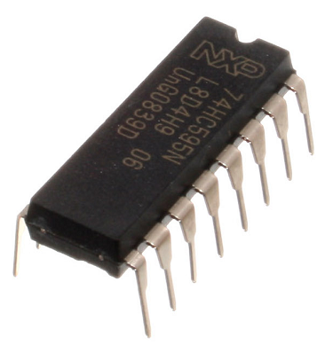
The shift register used on this page looks like this and costs around 60p to buy, depending on the shop,
The Circuit
Electronic components normally have a datasheet which explains how it works, what voltages it can tolerate and what each of the pins do. From the datasheet for this integrated circuit, the pinning diagram is as follows,
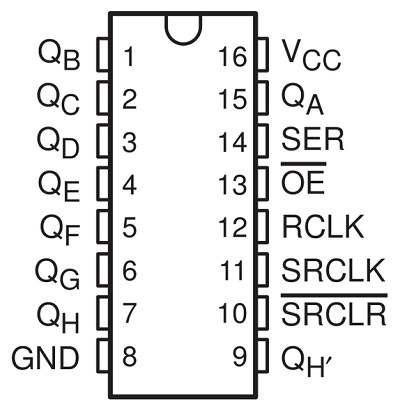
This looks a little complicated but can be understood if we take our time.
| Pin | Connection | Description |
|---|---|---|
| VCC | 3V | This provides power to the integrated circuit. |
| GND | GND | This is the connection to ground that completes our circuit. |
| QA-QH | LEDs 1 - 8 | These are the outputs. We connect them to the LEDs. |
| OE | GND | OE stands for output enable. The integrated circuit is enabled when we connect this to ground. |
| SRCLR | 3V | We need to connect this pin to the power to enable the shift register. |
| SER | Pin 0 | This is our data pin. We use this to send 1s and 0s to the shift register. |
| SRCLK | Pin 1 | We call this the clock pin. We use this to tell the shift register to accept an input. |
| RCLK | Pin 2 | We call this our latch pin. We use this to tell the shift register to output the mixture of high and low voltages we have previously sent. |
The notch on the integrated circuit tells you how to orient it when you put it into the breadboard. It goes at the top. Here is a diagram of the circuit you will need.
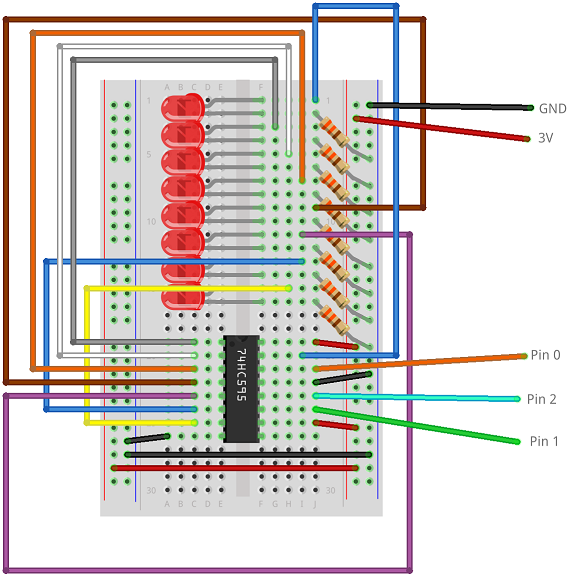
It looks complicated. It is easier to get the connections right if you follow the logic of the table above.
Programming
In this program, the variable value stores the pattern of LEDs we want to light from our 8. Use this Binary Counter to see how counting from 0 to 255 produces a pattern of 1s and 0s on the 8 binary place values. The bits variable stores a list of these 1s and 0s, created with a nifty piece of Python. In the example, with a value of 255, all of the LEDs should come on. Try 170 to light alternate LEDs.
from microbit import *

pin0.write_digital(0)
pin1.write_digital(0)
pin2.write_digital(0)
value = 255
bits = [value >> i & 1 for i in range(7,-1,-1)]
for i in range(7,-1,-1):
    print(bits[i])
    pin0.write_digital(bits[i])
    pin1.write_digital(1)
    pin1.write_digital(0)
pin2.write_digital(1)
pin2.write_digital(0)
The for loop that goes from 7 to 0 is the important one. We write the 1 or 0 to pin0 (data) to set the value of each bit. Then we write a 1 and then a 0 to pin1 (clock). When the loop is done, we write a 1 and then a 0 to pin2 (latch) to make the shift register output the pattern.
Using a single number like this can make it quite easy to do some patterns with the LEDs. The following program uses a loop to light all of the LEDs, adding one at a time. The numbers used in the list are all 1 less than the binary place values. Think about the idea of place value and you can explain how and why this works.
from microbit import *

pin0.write_digital(0)
pin1.write_digital(0)
pin2.write_digital(0)
for value in [1,3,7,15,31,63,127,255]:
    bits = [value >> i & 1 for i in range(7,-1,-1)]
    for i in range(7,-1,-1):
        print(bits[i])
        pin0.write_digital(bits[i])
        pin1.write_digital(1)
        pin1.write_digital(0)
    pin2.write_digital(1)
    pin2.write_digital(0)
    sleep(100)
Challenges
- There has to be something interesting that you can do with so many LEDs. You could use them to show the amount of roll being sensed by the accelerometer, turning on different LEDs depending on whether the micro:bit is tilted to the left or right.
- You could use some LEDs as a temperature indicator for a thermometer.
- You could separate the LEDS into 2 groups of 4 and use them as a scoreboard for a digital game of rock, paper, scissors. After each round, the user should press button A or button B depending on which player won the round. When a player reaches 4, they win the game.
- Pretty patterns can be made with this many LEDs. Look up a Larson Scanner. You can use the shift register to make one of these with your micro:bit.
- 8 bits make a byte. Turn the LEDs into a binary counter that counts from 0 to 255. Use the buttons and you can allow the user to move up and down through the numbers from 0 to 255.
- If you have an edge connector, swap pin0 for 8, 12 or 16. Then put a buzzer on pin0 and flash the lights along with notes from a tune or with each beat of a metronome you have made.