BBC Microbit
![]()


BBC micro:bit
RGB LED
Introduction
This is a photograph of an RGB LED.
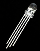
If you work from left to right in the photograph, the 4 legs of the LED correspond to BLUE, GROUND, GREEN & RED. The ground pin is shared by all 3 LEDs. This is called a common cathode RGB LED. The RGB LED allows us to turn each of the colours on and off. We can also mix different amounts of red, green and blue light to make the exact colours we want.
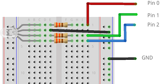
Study the diagram of the circuit carefully.
- The 4 legs of the RGB LED are placed in the breadboard so that each leg is on a different row of the breadboard.
- The longest leg of the LED is connected directly to GND on the micro:bit.
- A 200 OHM resistor is connected to each of the other legs of the LED.
- The red LED is connected to pin2.
- The green LED is connected to pin1.
- The blue LED is connected to pin0.
Task 1
Your first program is all about testing the connections in your circuit.
from microbit import *

b = pin0
g = pin1
r = pin2

# red
r.write_digital(1)
sleep(1000)
r.write_digital(0)
sleep(1000)

# green
g.write_digital(1)
sleep(1000)
g.write_digital(0)
sleep(1000)

# blue
b.write_digital(1)
sleep(1000)
b.write_digital(0)
sleep(1000)
The 3 variables r,g and b are used in this program to make it easier to remember which pin has which colour of LED connected to it.
Although the LEDs are in the same package, we can turn them on and off individually just as if they were separate LEDs.
Task 2
Whilst you can use the LEDs separately, it is more interesting to combine them to make new colours. Write a program to help you fill in the following table with the colour you make from different combinations of the LEDs
| RED | GREEN | BLUE | Colour Made |
|---|---|---|---|
| 1 | 1 | 1 | |
| 0 | 1 | 1 | |
| 1 | 1 | 0 | |
| 1 | 0 | 1 |
Task 3
Write a program that changes the colour that you see on the RGB LED every time you press one of the micro:bit buttons. Decide whether or not you want the choice of colour to be predictable (hard-coded) or generated at random.
Task 4
The word 'digital', means 'on or off'. So far, our LEDs have always been in one of these two states, on or off.
The following program uses analog_write() to vary the brightness of each of the 3 LEDs. That allows us to blend them to make even more colours. The values you can write with this statement range from 0 to 1023.
from microbit import *

b = pin0
g = pin1
r = pin2

r.write_analog(0)
g.write_analog(800)
b.write_analog(300)
Task 5
The following program contains a subroutine with parameters that can be used to set the colour blend efficiently.
from microbit import *

def light(red,green,blue):
    pin0.write_analog(blue)
    pin1.write_analog(green)
    pin2.write_analog(red)


light(1023,0,0)
sleep(1000)
light(0,0,0)
The last 3 lines of the program turn on the RED LED for a second before turning all of the LEDs off. Write a more interesting program with this subroutine.
Task 6
Write a program that displays the traffic light sequence. Work out how to blend the colours to make the amber light.
Look up the complete sequence of traffic lights and replicate it perfectly in your program.
Task 7
The following snippet of code generates a random integer from 0 to 1023.
from microbit import *
import random

a = random.randint(0,1023)
Use this technique and the procedure from Task 5 to write a program that blends random amounts of red, green and blue.
Task 8
Adapt and extend your program from Task 8 so that the LEDs are all off when the micro:bit starts up. Use a while true loop and, if the A button was pressed, generate 3 random numbers and use them to blend a colour on the RGB LED. Pressing the button again should generate a new random colour.