BBC Microbit
![]()


BBC micro:bit
LCD Digital Clock
Introduction
This project is a combination of two pieces of hardware explained previously. A 16x2 LCD character display is used to display the time being read from a DS3231 real time clock. This gives us a digital clock.
Circuit
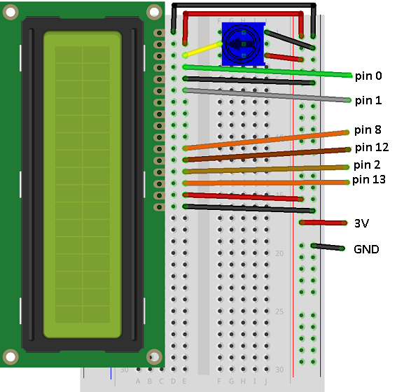
Start by connecting and testing the LCD display using a circuit like this,
Add the RTC component and connect as follows,
- Connect GND on the breakout to GND on the microbit.
- Connect VCC to 3V.
- Connect SDA to pin 20.
- Connect SCL to pin 19.
Programming
This is a straightforward copy and paste from the programs written to drive these two pieces of hardware.
from microbit import *

# pin connections
rs = pin0
enable = pin1
datapins = [pin8, pin12, pin2, pin13]

# commands
LCD_CLEARDISPLAY = 0x01
LCD_RETURNHOME = 0x02
LCD_ENTRYMODESET = 0x04
LCD_DISPLAYCONTROL = 0x08
LCD_CURSORSHIFT = 0x10
LCD_FUNCTIONSET = 0x20
LCD_SETCGRAMADDR = 0x40
LCD_SETDDRAMADDR = 0x80

# flags for display entry mode
LCD_ENTRYRIGHT = 0x00
LCD_ENTRYLEFT = 0x02
LCD_ENTRYSHIFTINCREMENT = 0x01
LCD_ENTRYSHIFTDECREMENT = 0x00

# flags for display on/off control
LCD_DISPLAYON = 0x04
LCD_DISPLAYOFF = 0x00
LCD_CURSORON = 0x02
LCD_CURSOROFF = 0x00
LCD_BLINKON = 0x01
LCD_BLINKOFF = 0x00

# flags for display/cursor shift
LCD_DISPLAYMOVE = 0x08
LCD_CURSORMOVE = 0x00
LCD_MOVERIGHT = 0x04
LCD_MOVELEFT = 0x00

# flags for function set
LCD_8BITMODE = 0x10
LCD_4BITMODE = 0x00
LCD_2LINE = 0x08
LCD_1LINE = 0x00
LCD_5x10DOTS = 0x04
LCD_5x8DOTS = 0x00


def InitDisplay():
    # at least 50ms after power on
    sleep(50)
    # send rs, enable low - rw is tied to GND
    rs.write_digital(0)
    enable.write_digital(0)
    write4bits(0x03)
    sleep(5)
    write4bits(0x03)
    sleep(5)
    write4bits(0x03)
    sleep(2)
    write4bits(0x02)
    send(LCD_FUNCTIONSET | 0x08, 0)
    sleep(5)
    send(LCD_FUNCTIONSET | 0x08, 0)
    sleep(2)
    send(LCD_FUNCTIONSET | 0x08, 0)
    sleep(2)
    send(LCD_FUNCTIONSET | 0x08, 0)
    sleep(2)
    send(LCD_DISPLAYCONTROL | LCD_DISPLAYON | LCD_CURSOROFF | LCD_BLINKOFF,0)
    clear()
    send(LCD_ENTRYMODESET | LCD_ENTRYLEFT | LCD_ENTRYSHIFTDECREMENT,0)

# high level commands
def clear():
    send(LCD_CLEARDISPLAY,0)
    sleep(2)

def home():
    send(LCD_RETURNHOME,0)
    sleep(2)

def setCursor(col, row):
    orpart = col
    if row>0:
        orpart = orpart + 0x40
    send(LCD_SETDDRAMADDR | orpart, 0)

def showText(t):
    for c in t:
        send(ord(c), 1)

def send(value, mode):
    rs.write_digital(mode)
    write4bits(value>>4)
    write4bits(value)

def pulseEnable():
    enable.write_digital(0)
    sleep(1)
    enable.write_digital(1)
    sleep(1)
    enable.write_digital(0)
    sleep(1)

def write4bits(value):
    for i in range(0,4):
        datapins[i].write_digital((value>>i) & 0x01)
    pulseEnable()

# RTC variables
addr = 0x68
buf = bytearray(7)

def bcd2dec(bcd):
    return (((bcd & 0xf0) >> 4) * 10 + (bcd & 0x0f))

def dec2bcd(dec):
    tens, units = divmod(dec, 10)
    return (tens << 4) + units

def get_time():
    i2c.write(addr, b'\x00', repeat=False)
    buf = i2c.read(addr, 7, repeat=False)
    ss = bcd2dec(buf[0])
    mm = bcd2dec(buf[1])
    if buf[2] & 0x40:
        hh = bcd2dec(buf[2] & 0x1f)
        if buf[2] & 0x20:
            hh += 12
    else:
        hh = bcd2dec(buf[2])
    wday = buf[3]
    DD = bcd2dec(buf[4])
    MM = bcd2dec(buf[5] & 0x1f)
    YY = bcd2dec(buf[6])+2000
    return [hh,mm,ss,YY,MM,DD,wday]


# Start Display
InitDisplay()
while True:
    tm = get_time()
    str_time = '{0:02d}'.format(tm[0]) + ":" + '{0:02d}'.format(tm[1]) + ":" + '{0:02d}'.format(tm[2])
    str_date = '{0:02d}'.format(tm[5]) + "/" + '{0:02d}'.format(tm[4]) + "/" + '{0:04d}'.format(tm[3])
    setCursor(0,0)
    showText(str_time)
    setCursor(0,1)
    showText(str_date)
    sleep(500)
It's a little funny on the updating but more than usable for telling the time. Not showing the seconds, would mean that the display needed less frequent updating and would avoid the slow code I have written from making the seconds look a little uneven.
Challenges
- The clock needs a nice alarm. You should have a few GPIO spare for adding a buzzer and maybe some LEDs or even Neopixels for some cool effects when the alarm goes off.
- Using buttons to make it possible to set the alarm and turn it off/on would be useful.