BBC Microbit
![]()


BBC micro:bit
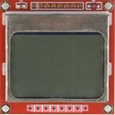
Nokia 5110 LCD
Introduction
This page describes an attempt to make the micro:bit display an image on a Nokia 5110 LCD display.
The Nokia 5110 was a mobile phone that dates back to what most micro:bit owners would call the olden days. When the phones were no longer being manufactured, some electronics companies started to harvest the screens from them and mount them on breakout boards for hobbyists to use. A couple of versions exist, from Sparkfun and Seeedstudio. They aren't the shiniest of displays but are about the cheapest graphical LCD out there, usually under £10.
You need 5 pins to control the display. An edge connector is a must for this project.
The Circuit
This will depend on the breakout board you have. Some look like this,
My one is on a blue PCB and has its pins in a different order.
For the program below, connect up the pins to the micro:bit as follows,
| LCD Pin | micro:bit Pin |
|---|---|
| RST | pin 0 |
| CE | pin 1 |
| DC | pin 8 |
| DIN | pin 12 |
| CLK | pin 2 |
| VCC | 3V |
| BL | 3V |
| GND | GND |
I also connected a 0.1uf capacitor from VCC to GND.
BL is the backlight. You don't need to connect this to be able to see the display. I prefer not to use it.
Programming
This code will display a bitmap on the screen. The bitmap is an image of Tux, the Linux penguin.
from microbit import *
import array

tux = bytearray(b'\x00\x00\x00\x00\x00\x00\x00\x00\x00\x00,\x00\x00\x00\x00\x00\x00\x00\x00\x00\x00\x00\x00\x00\x00\x00\x00\x00\x00\x00\x00\xC0\xE0\xF0\xF0\xF0\xF0\xF0\xF0\xE0\xE0\xC0\x80\x00\x00\x00\x00\x00\x00\x00\x00\x00\x00\x00\x00\x00\x00\x00\x00\x00\x00\x00\x00\x00\x00\x00\x00\x00\x00\x00\x00\x00\x00\x00\x00\x00\x00\x00\x00\x00\x00\x00\x00\x00\x00\x00\x00\x00\x00\x00\x00\x00\x00\x00\x00\x00\x00\x00\x00\x00\x00\x00\x00\x00\x00\x00\x00\x00\x00\x00\x00\x00\x00\x00\x00\xFF\xB1\x5D\x89\x8F\x89\x5D\x11\x3F\xFF\xFF\xFF\xF8\x00\x00\x00\x00\x00\x00\x00\x00\x00\x00\x00\x00\x00\x00\x00\x00\x00\x00\x00\x00\x00\x00\x00\x00\x00\x00\x00\x00\x00\x00\x00\x00\x00\x00\x00\x00\x00\x00\x00\x00\x00\x00\x00\x00\x00\x00\x00\x00\x00\x00\x00\x00\x00\x00\x00\x00\x00\x00\x00\x00\x00\x00\x00\x00\x00\x00\x00\xE0\xF0\x78\x3E\x03\x01\x01\x02\x02\x02\x02\x02\x01\x01\x03\x1F\x7F\xFF\xFE\xF8\xF0\xC0\x00\x00\x00\x00\x00\x00\x00\x00\x00\x00\x00\x00\x00\x00\x00\x00\x00\x00\x00\x00\x00\x00\x00\x00\x00\x00\x00\x00\x00\x00\x00\x00\x00\x00\x00\x00\x00\x00\x00\x00\x00\x00\x00\x00\x00\x00\x00\x00\x00\x00\x00\x00\x00\x00\x00\x00\x00\x00\x00\xC0\x3C\x3F\x7F\xC3\x80\x00\x00\x00\x00\x00\x00\x00\x00\x00\x00\x00\x00\x80\x40\x7F\xFF\xFF\xFF\xFF\xFF\x80\x00\x00\x00\x00\x00\x00\x00\x00\x00\x00\x00\x00\x00\x00\x00\x00\x00\x00\x00\x00\x00\x00\x00\x00\x00\x00\x00\x00\x00\x00\x00\x00\x00\x00\x00\x00\x00\x00\x00\x00\x00\x00\x00\x00\x00\x00\x00\x00\x00\x00\x00\x00\x00\x26\x59\x41\x41\x80\x80\x80\x80\x00\x03\x07\x9E\xE4\xE0\xE0\x60\x60\x60\x60\x60\x70\x78\x7B\xFC\x00\x00\x01\x01\x01\x80\x47\x48\x28\x10\x00\x00\x00\x00\x00\x00\x00\x00\x00\x00\x00\x00\x00\x00\x00\x00\x00\x00\x00\x00\x00\x00\x00\x00\x00\x00\x00\x00\x00\x00\x00\x00\x00\x00\x00\x00\x00\x00\x00\x00\x00\x00\x00\x00\x00\x00\x00\x00\x00\x00\x00\x00\x00\x00\x00\x00\x00\x00\x01\x01\x01\x01\x00\x00\x00\x00\x00\x00\x00\x00\x00\x00\x00\x00\x01\x01\x01\x01\x01\x00\x00\x00\x00\x00\x00\x00\x00\x00\x00\x00\x00\x00\x00\x00\x00\x00\x00\x00\x00\x00\x00\x00\x00\x00\x00\x00\x00\x00\x00\x00\x00\x00\x00\x00\x00')

def LCDWrite(dc, data):
    pin8.write_digital(dc)
    pin1.write_digital(0)
    pin2.write_digital(0)
    bits = [data >> i & 1 for i in range(7,-1,-1)]
    for j in range(0,8):
        pin12.write_digital(bits[j])
        pin2.write_digital(1)
        pin2.write_digital(0)
    pin1.write_digital(1)
    return

def LCDClear():
    for i in range(0,504):
        LCDWrite(1, 0x00)
    return


def LCDLoadBitmap(bmp):
    for i in range(0,504):
        LCDWrite(1,bmp[i])
    return


# Initialise the display

pin0.write_digital(0)
pin0.write_digital(1)
LCDWrite(0, 0x21)
LCDWrite(0, 0xB1)
LCDWrite(0, 0x04)
LCDWrite(0, 0x14)
LCDWrite(0, 0x0C)
LCDWrite(0, 0x20)
LCDWrite(0, 0x0C)

# Display Test Bitmap
LCDClear()
LCDLoadBitmap(tux)
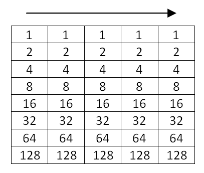
To follow this, you need to understand binary. The display is made up of 84x48 pixels. The display deals with them 8 at a time, in columns. Starting at the top left of the screen, we have to send 504 bytes in a row to set the pixels of the display. Treating the pixels as a binary number, with the units at the top of the column, we describe the image we want to display using numbers. When we have done the first 84 columns of 8 pixels, we move down 8 pixels and do another 84 columns, repeating until we have done a total of 504 bytes. This makes up our image.
Challenges
This is the start of some proper hardware hacking. The program code on this page was worked out from reading about how to do this with an Arduino. If you search the Arduino Playground tutorials, you will find some code there. Work hard and you will be able to improve on what you see here, perhaps even get a rudimentary font going or a display engine for your projects. The graphical display opens up the possibility of games too.