BBC Microbit
![]()


BBC micro:bit
7 Segment Display
Introduction
Seven segment displays are a very common way of displaying numbers and are still used a lot for clocks, calculators and handheld instruments.
They get their name from the number of hexagons or segements that are used to represent the characters. Each one of these segements contains an LED. Look at the image of the Sparkfun 7 Segment Display.
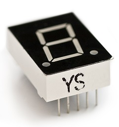
The display has 8 segments, there is also a decimal point.
This project is based on a single one of these displays, giving us the chance to display a single digit on the display. This would work well with the concentration game where it is not possible to show a running score. The decimal point could be lit up to represent tens. No one gets a score of 20 or more in that game.
The single segment also gives us a chance to see, in principle, how we make the component display different numbers.
Circuit
The display consists of 8 LEDs. A standard LED will usually have two pins. One of those pins is positive. We call this the anode and connect it to an output or power pin. The other pin is negative. We call that the cathode and connect it to GND. We also use a resistor to limit the current going through the LED. In this circuit 220 Ohm resistors are used.
This display is called a common anode display. All of the LEDs anodes have been wired together. If we apply power through the anode, we can turn each LED on by writing a 0 or LOW signal to the segment's cathode. Writing a 1 turns it off.
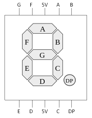
These displays are always a little bit of a mission to set up. There are lots of wires and the pins are often placed to allow easy routing to the LEDs in the package to keep it compact. This is the pinning diagram from the datasheet that we will be working from,
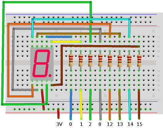
When making a circuit, try to think about what connects to what. The breadboard diagrams give you an impression of what things look like but it is sometimes easier to work directly from the schematic diagram you see above rather than a breadboard diagram like this,
Programming
This is the basic code to write digits to the display. Binary is a convenient way to use numbers to represent the different configurations of the LEDs needed for each digit. The patterns in the list called digits are in digit order from 0 to 9. Their position in the list matches their value.
from microbit import *

pins = [pin0, pin1, pin8, pin12, pin2, pin13, pin14, pin15]
digits = [0b00000011,0b10011111,0b00100101, 0b00001101,0b10011001,
0b01001001,0b01000001,0b00011111,0b00000001,0b00011001]

def WriteDigit(d):
    bits = [digits[d] >> i & 1 for i in range(7,-1,-1)]
    for p in range(0,8):
            pins[p].write_digital(bits[p])

while True:
    for i in range(0,10):
        WriteDigit(i)
        sleep(1000)
This code also shows how you can make variables to represent the pins. The pins list is in A - G order of the segments with the decimal point at the end. We can use a loop to write to all of the pins. The bits list is created with a neat Pythonic statement. The statement uses a bitwise operator, right shift and a logical operator, and to work out whether each of the binary digits is a 1 or a 0.
Challenges
- To turn off the display, write a 1 (HIGH) to all of the cathodes. You can use a for loop to do this. If you can turn off the display, you can make the digits blink.
- Now that you have the techniques you need, find ways to implement this with one of your projects or games.