BBC Microbit
![]()


BBC micro:bit
Bit:Commander
Introduction
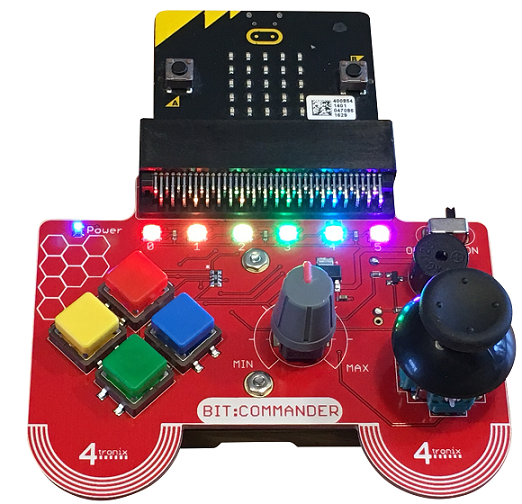
The Bit:Commander is a breakout board for the micro:bit made by 4tronix, who also make the Bit:Bot and Bit:2:Pi. Breakout board with micro:bit edge connector based on a game controller. The board is powered by 3xAA batteries mounted on the underside. This also powers the micro:bit. There is a main power on/off switch. The board components are,
- 4 push buttons with coloured square caps (Red, Blue, Green, Yellow)
- Potentiometer
- 2 Axis Joystick and switch
- Piezo Buzzer
- 6 Neopixels
The components connect to different micro:bit GPIO pins. All parts work without the need for connections or soldering. The design clearly favours end use as a controller for a game, robot or some other circuit. The variety of inputs lend themselves well to a range of applications. The buzzer and lights, as well as the LED matrix on the micro:bit can be used as indicators or to provide feedback/alerts. The portability makes it useful in projects where the memory or circuit means that you are using 2 micro:bits. It's nice not to have to poke your fingers through a nest of jumper wires to activate a circuit.
Since the board uses analog and digital inputs and outputs, it's a good platform on which to learn the basic principles of programming for components. The board also nicely extends the micro:bit's functionality making a portable unit that can be disconnected from the USB.
Pinout
| Component | Pin |
|---|---|
| Buzzer | 0 |
| Potentiometer | 0 |
| Joystick X | 1 |
| Joystick Y | 2 |
| Joystick Button | 8 |
| Red Pushbutton | 12 |
| Blue Pushbutton | 15 |
| Green Pushbutton | 14 |
| Yellow Pushbutton | 16 |
| Neopixels | 13 |
The buzzer and potentiometer share pin 0. You can use the components separately. When reading the potentiometer after the buzzer has been used, you may need to digital_read pin 0 to reset the pin after it has been used for playing tones.
Quick Test
If you have access to a serial monitor, like the REPL window in Mu, this program will show you the features of the board in one go, outputting readings from the inputs after the outputs have been tested.
from microbit import *
import music
import neopixel

# Initialise neopixels
npix = neopixel.NeoPixel(pin13, 6)

# Define some colours
red = (64,0,0)
green = (0,64,0)
blue = (0,0,64)
nocol = (0,0,0)

# light all neopixels with given colour
def light_all(col):
    for pix in range(0, len(npix)):
        npix[pix] = col
    npix.show()

# wipe a colour across pixels one at a time
def wipe(col, delay):
    for pix in range(0, len(npix)):
        npix[pix] = col
        npix.show()
        sleep(delay)

def read_joy():
    return pin1.read_analog(), pin2.read_analog(), pin8.read_digital()

def read_buttons():
    # red, blue, green, yellow
    btns = [pin12,pin15,pin14,pin16]
    return [p.read_digital() for p in btns]

def read_pot():
    return pin0.read_analog()

def play_tune():
    music.play(music.BADDY)
    pin0.read_digital()


light_all(red)
play_tune()
wipe(blue,250)
while True:
    x,y,j = read_joy()
    btns = read_buttons()
    p = read_pot()
    print(x,y, j, btns, p)
    sleep(20)
The readings you see being printed are the x and y values for the joystick, whether or not the joystick button is pressed, the state of the buttons and finally, the reading from the potentiometer.
I ran this as a first test to see some use of all of the parts of the board. Watching the readings as you press and move the inputs is an easy way to see how things work.
The Rest Of The Section
There are already pages on the site that look at how to deal with the individual components of the board. I chose to use the board to reflect a little more on each of these, like the buttons and the dial, and work out better approaches to programming for them. I also converted some older programs to use the Bit:Commander as an input and found them easier to use as a result.