BBC Microbit
![]()


BBC micro:bit
SNES Controller
Introduction
The SNES (Super Nintendo Entertainment System) is a games console that was released in 1992 in the UK. The original controller used 2 x 4021 PISO input shift registers connected to 12 buttons. The NES controller was based on one of these shift registers. Since I'd already got one of these to work on the micro:bit, I figured it would be easy enough to connect the controller to the micro:bit and read the button presses.
Most modern controllers have their own microcontroller and communicate with a host console via bluetooth, RF or using the i2c protocol. The SNES model is beautifully simple, the controller is more of an extension to the circuitry of the console than a separate component in itself.
There are a few companies that still make SNES controllers with the original 7-pin connector. Adafruit have some lovely material on how to turn one of these into a USB game pad, wired and wireless. Cool as that is, I wanted to keep my one microcontroller friendly. Although I've seen Arduino hack photographs of people poking jumpers into the connector, I found that they fell out too much. I found a cheap PCB female connector and soldered it onto some protoboard with some female headers to make an adapter to connect to the micro:bit and my other microcontroller boards.
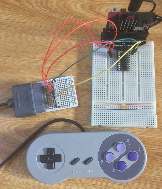
The female socket has pretty big pins and they aren't nicely spaced out. They fit through the Adafruit perma-proto board holes but won't go through normal perfboard. You can direct the pins and nudge them into some holes. It's awkward but possible to get the socket flush to the protoboard.
Circuit
Since we're dealing with shift registers, we are going to need to connect a latch, clock and data pins. We'll also need power and ground signals. 5 of the 7 pins on the controller need to be connected. The other two are unused on this device.
The pins on the connector are arranged in a group of 4 and a group of 3. Use this to orient yourself when making connections.
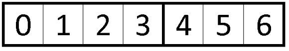
Using the numbers above, the pins have the following roles,
- 0 - 3V3
- 1 - Clock
- 2 - Latch
- 3 - Data
- 6 - GND
In my test circuit I used pin 0 for the data pin, pin 1 for the clock, and pin 2 for the latch. Any 3 digital pins are fine for this with small changes to the example code.
Programming
Here's a simple base class to start things off,
from microbit import *

class SNES:
    # set up which micro:bit pins to use
    def __init__(self, latch, clock, data):
        self.latch = latch
        self.clock = clock
        self.data = data
    # take a reading and return a 16bit integer
    def getReading(self):
        self.latch.write_digital(1)
        self.latch.write_digital(0)
        word = 0
        for i in range(16):
            self.clock.write_digital(0)
            word = word + (self.data.read_digital()<<i)
            self.clock.write_digital(1)
        return word
    # create and return dictionary of button names and the readings
    def info(self):
        reading = self.getReading()
        keys = ["0","0","0","0","RSH","LSH","X","A","R","L","D","U","Start","Select","Y","B"]
        bits = [reading >> i & 1 for i in range(15,-1,-1)]
        return dict(zip(keys,bits))
    # create and return a list of buttons that have been pressed
    def pressed(self):
        d = self.info()
        output = []
        for k in d:
            if d[k]!=1:
                output.append(k)
        return output
There are 3 methods for reading the controller. The getReading() method creates a 16 bit integer corresponding to the button presses. If you print this out with binary formatting, you can see how the integer changes as you press different buttons and combinations of buttons. Reading the 16 bit integer is handy when you want to quickly check for a change in any of the button states before working out which one was pressed.
You only get output if a button is pressed. This code shows us how the binary pattern changes as buttons are pressed. A 0 means a button being pressed. You'll see a stream of presses being registered each time you hold down the button. That's fixable with a different approach to the coding. This is worth it for the information though - it was needed to make the second method.
from microbit import *

class SNES:
    # set up which micro:bit pins to use
    def __init__(self, latch, clock, data):
        self.latch = latch
        self.clock = clock
        self.data = data
    # take a reading and return a 16bit integer
    def getReading(self):
        self.latch.write_digital(1)
        self.latch.write_digital(0)
        word = 0
        for i in range(16):
            self.clock.write_digital(0)
            word = word + (self.data.read_digital()<<i)
            self.clock.write_digital(1)
        return word
    # create and return dictionary of button names and the readings
    def info(self):
        reading = self.getReading()
        keys = ["0","0","0","0","RSH","LSH","X","A","R","L","D","U","Start","Select","Y","B"]
        bits = [reading >> i & 1 for i in range(15,-1,-1)]
        return dict(zip(keys,bits))
    # create and return a list of buttons that have been pressed
    def pressed(self):
        d = self.info()
        output = []
        for k in d:
            if d[k]!=1:
                output.append(k)
        return output

# create a pad instance
pad = SNES(pin2,pin1,pin0)
while True:
    reading = pad.getReading()
    if reading!=65535:
        print('{:016b}'.format(reading))
    sleep(10)
The second method for reading, info() makes a dictionary of the button names and the readings. It was useful for checking that I'd worked out which bits of my integer reading corresponded to which button on the controller.
Here, I played around with the timings and a follower variable to capture cleanish presses of the start button.
from microbit import *

class SNES:
    # set up which micro:bit pins to use
    def __init__(self, latch, clock, data):
        self.latch = latch
        self.clock = clock
        self.data = data
    # take a reading and return a 16bit integer
    def getReading(self):
        self.latch.write_digital(1)
        self.latch.write_digital(0)
        word = 0
        for i in range(16):
            self.clock.write_digital(0)
            word = word + (self.data.read_digital()<<i)
            self.clock.write_digital(1)
        return word
    # create and return dictionary of button names and the readings
    def info(self):
        reading = self.getReading()
        keys = ["0","0","0","0","RSH","LSH","X","A","R","L","D","U","Start","Select","Y","B"]
        bits = [reading >> i & 1 for i in range(15,-1,-1)]
        return dict(zip(keys,bits))
    # create and return a list of buttons that have been pressed
    def pressed(self):
        d = self.info()
        output = []
        for k in d:
            if d[k]!=1:
                output.append(k)
        return output

# create a pad instance
pad = SNES(pin2,pin1,pin0)
print("Press Start")
last = 1
while True:
    reading = pad.info()
    current = reading['Start']
    if current!=last and current==0:
        print("Pressed Start")
        print("Release Start")
        sleep(100)
    elif current!=last and current==1:
        print("Released Start")
        print("Press Start")
        sleep(100)
    last = current
    sleep(10)
The third method, pressed() outputs a list of the keys pressed, my short names for the buttons. You don't get any output if no buttons are pressed.
from microbit import *

class SNES:
    # set up which micro:bit pins to use
    def __init__(self, latch, clock, data):
        self.latch = latch
        self.clock = clock
        self.data = data
    # take a reading and return a 16bit integer
    def getReading(self):
        self.latch.write_digital(1)
        self.latch.write_digital(0)
        word = 0
        for i in range(16):
            self.clock.write_digital(0)
            word = word + (self.data.read_digital()<<i)
            self.clock.write_digital(1)
        return word
    # create and return dictionary of button names and the readings
    def info(self):
        reading = self.getReading()
        keys = ["0","0","0","0","RSH","LSH","X","A","R","L","D","U","Start","Select","Y","B"]
        bits = [reading >> i & 1 for i in range(15,-1,-1)]
        return dict(zip(keys,bits))
    # create and return a list of buttons that have been pressed
    def pressed(self):
        d = self.info()
        output = []
        for k in d:
            if d[k]!=1:
                output.append(k)
        return output

# create a pad instance
pad = SNES(pin2,pin1,pin0)
while True:
    reading = pad.pressed()
    if reading!=[]:
        print(reading)
    sleep(10)
In this example, you use the D pad to move a flashing dot cursor around the LED matrix on the micro:bit. You press the B button to toggle different LEDs on and off.
from microbit import *
import random

class SNES:
    # set up which micro:bit pins to use
    def __init__(self, latch, clock, data):
        self.latch = latch
        self.clock = clock
        self.data = data
    # take a reading and return a 16bit integer
    def getReading(self):
        self.latch.write_digital(1)
        self.latch.write_digital(0)
        word = 0
        for i in range(16):
            self.clock.write_digital(0)
            word = word + (self.data.read_digital()<<i)
            self.clock.write_digital(1)
        return word

x = 2
y = 2
tick = -1

grid = [
    [0,0,0,0,0],
    [0,0,0,0,0],
    [0,0,0,0,0],
    [0,0,0,0,0],
    [0,0,0,0,0]
    ]

def Toggle(tx, ty):
    grid[tx][ty] ^= 1

def DrawGame(t):
    img = Image('00000:'*5)
    for cy in range(0,5):
        for cx in range(0,5):
            img.set_pixel(cx, cy, grid[cx][cy]*5)
    img.set_pixel(x, y, (t % 2)*9)
    return img

# create a pad instance
pad = SNES(pin2,pin1,pin0)
lastpad = 15
lastbutton = 1
while True:
    tick +=1
    if tick==2:
        tick = 0
    # read controller
    reading = pad.getReading()
    # get button B reading
    currentbutton = reading & 1
    # create a pad nibble
    currentpad = (reading >> 4) & 15
    # do movements RLDU
    if currentpad!=lastpad:
        if currentpad == 14:
           y -= 1
        elif currentpad == 13:
           y += 1
        elif currentpad == 7:
           x += 1
        elif currentpad == 11:
           x -= 1
        sleep(100)
    # keep on grid
    x = max(0, min(x, 4))
    y = max(0, min(y, 4))
    # check for button press
    if currentbutton==0 and currentbutton!=lastbutton:
        Toggle(x, y)
        sleep(200)
    # update screen
    i = DrawGame(tick)
    display.show(i)
    lastbutton = currentbutton
    lastpad = currentpad
    sleep(50)
If you look carefully at how the buttons are being read, you'll see that some simple logical operations are used to extract the part of the binary pattern that we want. Button B is the first bit of our reading. If we do a bitwise and with 1, we find the value of the first bit. The bits that correspond to the Dpad are 4-7. If we shift them to the right 4 places and do a logical and with 15, we get a nibble corresponding to the button state. The Dpad allows for 2 buttons to be pressed at the same time. You can read the diagonals here too, although they have been counted out of this example. Working directly with the bit pattern is likely to be the most efficient way to get the readings although you might build some of that functionality into the class.
Challenges
- Overkill for an LED matrix game but luxurious when you want quick reliable readings for direction. Convert some of those matrix games to work with the controller.
- You have 12 buttons. Lots of input options for your circuits. How about some music with the buzzer or Neopixel control?
- To understand the Dpad reading in the last example on this page, you need to think about the binary for the numbers used. There are 4 bits representing the button presses. 15 would be no buttons pressed. You can press the diagonals and get a reading on 2 buttons. Work out the binary patterns for the diagonal movements and code for those too.
- Work out a system for entering text using the buttons and use to for an LCD display or to enter text for scrolling messages and much fun.
- This would be great for controlling a robot over radio.
- Use the controller for a larger matrix connected to the micro:bit, like one of the Pimoroni pHATs or the Adafruit charlieplexed matrix.