BBC Microbit
![]()


BBC micro:bit
Rainbow Hat
Introduction
The Rainbow HAT is a Raspberry Pi accessory designed by the electronics company Pimoroni. It has a lot of electronics crammed into the HAT, an alphanumeric 4 digit display, 7 APA102 (dot star) pixels, a BMP280 temperature and pressure sensor, three touch pads, 3 LEDs, a buzzer and some pins broken out. It's meant for GPIO and IOT projects on the Raspberry Pi. All of its parts can be made to work with the micro:bit though.
Here is an image of the HAT on a 4tronix Bit:2:Pi.
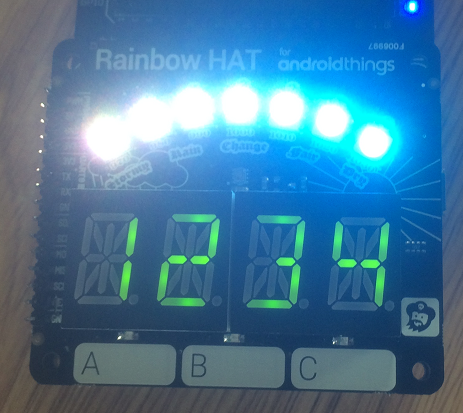
Rainbow HAT Exploration
There is a lot on the Rainbow HAT and the accessory is meant for a much more powerful controller than the micro:bit. Trying to write a single class to encapsulate all of the functionality of the HAT would not leave much room for an application of the device. Instead, I've concentrated on getting the individual parts of the HAT to work.
Each of the parts of the HAT has lots of possible uses in a variety of applications of the micro:bit. Using them all together will need some thought about memory and using the file system. This page is about ways to use the individual parts of the HAT.
The APA102 Pixels
The pixels are the same ones that are on the Blinkt. This time though, they are connected to SPI pins. On the Bit:2:Pi, you need the SPI jumpers. That means that micro:bit pin13 is connected to SCLK/BCM11/GPIO23 on the HAT, pin14 to MISO/BCM9/GPIO21 and pin15 to MOSI/BCM10/GPIO19 if you are using jumper wires.
I've left the class pretty sparse. You can adapt some code from the Blinkt and Neopixel pages and add your own methods. To save space, I've set the brightness to 255 (full) for each of the pixels. You can write in the functionality for changing the brightness (a value from 224 to 255) or use the RGB values alone to achieve a similar effect.
from microbit import *

class dotstar:

    def __init__(self, num_pix):
        self.num_pixels = num_pix
        # brightness,blue, green, red
        self.pixels = [[255,0,0,0]] * num_pix
        spi.init(baudrate=1000000,bits=8,mode=0, sclk=pin13, mosi=pin15, miso=pin14)
        self.show()

    def clear(self):
        for x in range(self.num_pixels):
            self.pixels[x] = [255,0,0,0]

    def set_pix(self,pix,r,g,b):
        self.pixels[pix] = [255,b,g,r]

    def set_all(self,r,g,b):
        for i in range(self.num_pixels):
            self.pixels[i] = [255,b,g,r]

    def show(self):
        # sof
        spi.write(b'\x00\x00\x00\x00')
        for i in range(self.num_pixels):
            spi.write(bytes(self.pixels[i]))
        # eof
        spi.write(b'\xff\xff\xff\xff')


dots = dotstar(7)
# red
dots.set_all(200,0,0)
dots.show()
sleep(3000)
# green
dots.set_all(0,200,0)
dots.show()
sleep(3000)
# blue
dots.set_all(0,0,200)
dots.show()
sleep(3000)
# clear
dots.clear()
dots.show()
for i in range(7):
    dots.set_pix(i,128>>i,0,0)
    dots.show()
    sleep(500)
If you are using the other features of the HAT, and have the SPI pins connected, you might get some LEDs on. You might need to include enough code to clear the pixels when you are using other parts of the HAT. This is enough to set the LEDs to off. If you wanted them all to be set to one colour at the start of a project, just change the bytes in the loop, remembering that they are in the order BGR.
spi.init(baudrate=1000000,bits=8,mode=0, sclk=pin13, mosi=pin15, miso=pin14)
spi.write(b'\x00\x00\x00\x00')
for i in range(7):
    spi.write(b'\xff\x00\x00\x00')
spi.write(b'\xff\xff\xff\xff')
The Alphanumeric Display
The display on the Rainbow HAT is the same as the one on the Four Letter pHAT. I'd already got that to work. The code for that is a little bulky, so I trimmed it down a little.
Pin Connections
I used a 4tronix Bit:2:Pi to connect the Rainbow HAT, making sure the i2c jumpers were in the correct place. Otherwise, you need to make the following connections.
| Connection | Raspberry Pi | micro:bit |
|---|---|---|
| Power LED | 5V | 5V |
| Power IC | 3V3 | 3V |
| Ground | GND | GND |
| Data | Pin 2 | Pin 20 |
| Clock | Pin 3 | Pin 19 |
from microbit import *

class fourletter:
    SEG_ADD             = 0x70
    SEG_BLINK           = 0x80
    SEG_BRIGHT          = 0xE0
    font = [0x0,0x6,0x220,0x12ce,0x12ed,0xc24,0x235d,0x400,0x2400,0x900,
        0x3fc0,0x12c0,0x800,0xc0,0x0,0xc00,0xc3f,0x6,0xdb,0x8f,0xe6,
        0x2069,0xfd,0x7,0xff,0xef,0x1200,0xa00,0x2400,0xc8,0x900,
        0x1083,0x2bb,0xf7,0x128f,0x39,0x120f,0xf9,0x71,0xbd,0xf6,
        0x1200,0x1e,0x2470,0x38,0x536,0x2136,0x3f,0xf3,0x203f,0x20f3,
        0xed,0x1201,0x3e,0xc30,0x2836,0x2d00,0x1500,0xc09,0x39,0x2100,
        0xf,0xc03,0x8,0x100,0x1058,0x2078,0xd8,0x88e,0x858,0x71,0x48e,
        0x1070,0x1000,0xe,0x3600,0x30,0x10d4,0x1050,0xdc,0x170,0x486,
        0x50,0x2088,0x78,0x1c,0x2004,0x2814,0x28c0,0x200c,0x848,0x949,
        0x1200,0x2489,0x520]

    def __init__(self):
        self.buffer = bytearray([0]*16)
        i2c.write(self.SEG_ADD,b'\x21',repeat=False)
        self.blink_rate(0)
        self.set_brightness(15)
        self.update_seg()

    def write_reg(self,reg,value):
        i2c.write(self.SEG_ADD, bytes([reg,value]), repeat=False)

    def blink_rate(self, b):
        b=0 if b>3 else b
        i2c.write(self.SEG_ADD,bytes([self.SEG_BLINK | 1 | (b << 1)]), repeat=False)

    def set_brightness(self,b):
        b = 15 if b>15 else b
        i2c.write(self.SEG_ADD,bytes([self.SEG_BRIGHT | b]), repeat=False)

    def update_seg(self):
        data = bytearray([0]) + self.buffer
        i2c.write(self.SEG_ADD,data,repeat=False)

    def clear(self):
        self.buffer = bytearray([0]*16)

    def raw_digit(self, value, position):
        self.buffer[position*2]   = value & 0xFF
        self.buffer[position*2+1] = (value >> 8) & 0xFF

    def set_digit(self, value, position):
        self.raw_digit(self.font[ord(value)-32], position)

    def print_str(self, value, ralign=True):
        pos = (4-len(value)) if ralign else 0
        for i, ch in enumerate(value):
            self.set_digit(ch,i+pos)

    def set_decimal(self, decimal, pos):
        if pos < 0 or pos > 3:
            return
        # Set bit 14
        if decimal:
            self.buffer[pos*2+1] |= (1 << 6)
        else:
            self.buffer[pos*2+1] &= ~(1 << 6)


fl = fourletter()
# four letter strings
fl.print_str("Byte")
fl.update_seg()
sleep(5000)
fl.clear()
fl.update_seg()
# test decimals
for i in range(4):
    fl.set_decimal(True,i)
    fl.update_seg()
    sleep(500)
sleep(1000)
fl.clear()
fl.update_seg()
sleep(1000)
for d in range(4):
    fl.set_digit(str(d),d)
    fl.update_seg()
    sleep(500)
The main and pretty much only optimisation here is with the font. There is still some work to do with the class to get a scrolling effect for the text and a neat way to work with decimal numbers.
The Buzzer
The buzzer on the HAT is connected to BCM13/GPIO33 on the Raspberry Pi. With the Bit:2:Pi, you need to run a jumper from pin0 to this GPIO pin. If you are poking wires in the HAT, make the same connection and make sure that the HAT's GND connection is made. Here is a quick test to see if that works, using the built-in tunes.
from microbit import *
import music

built_in_tunes = [music.DADADADUM, music.ENTERTAINER, music.PRELUDE,
music.ODE, music.NYAN, music.RINGTONE, music.FUNK, music.BLUES,
music.BIRTHDAY, music.WEDDING, music.FUNERAL, music.PUNCHLINE,
music.PYTHON, music.BADDY, music.CHASE, music.BA_DING,
music.WAWAWAWAA, music.JUMP_UP, music.JUMP_DOWN, music.POWER_UP,
music.POWER_DOWN]
while True:
    for tune in built_in_tunes:
        music.play(tune)
        sleep(5000)
Touch & LEDs
The three touch pads at the front of the HAT, labelled, A-C, are connected to GPIO40,38 and 36 on the Raspberry Pi. I connected these to micro:bit pins 16, 12 and 8. In front of each of the pads is an LED. These are red, green and blue and are on the Pi GPIO pins 31, 35 and 37. I connected these to micro:bit pins 0, 1 and 2.
There are 6 GPIO pins required for this. I used pins 0, 1 and 2 on the micro:bit for the LEDs. That leaves the chance for some PWM, assuming no buzzer being used. This is where the first snag crops up with the HAT. The touch pins need the input pins to be pulled high with internal resistors. The micro:bit pulls them down by default. When pins 0-2 are read like touch inputs, they should be pulled up, but that rules out your PWM pins for other purposes or for the LEDs. My bodge is to write a high signal to the digital pins just before reading them. This gave me clear enough readings to work with but will no doubt rightly anger someone more expert in the field than me. You could change the pins around as you like. Here is a test version to light the LEDs when each pad is touched.
from microbit import *

leds = [pin0,pin1,pin2]
pads = [pin16,pin12,pin8]
while True:
    for i in range(3):
        pads[i].write_digital(1)
        if pads[i].read_digital()==0:
            leds[i].write_digital(1)
        else:
            leds[i].write_digital(0)
    sleep(10)
The Temperature & Pressure
The temperature and pressure sensor is a BMP280, which we connect to via i2c. The chip address is 0x77. This was the hardest of the components to make work. I've tried and failed quite a few times to get decent readings from this sensor. The readings I get now seem plausible. The temperature sensor is going to read high, because of the heat generated by the electronics around the HAT. I get a reading slightly lower and more sensitive than the built in temperature on the micro:bit. It rises as I expect when I blow on the board and settles down a little when I stop. It does get warmer, the more the surrounding parts heat up. The pressure reading I get is in the right area. Local weather stations report pressure with an adjustment for the altitude of the station. When I use online calculators, my results seem to make sense.
The sensor is connected to the i2c pins. If you are using the Bit:2:Pi, make sure that you have the i2c jumpers set, otherwise, use the same connections as for the alphanumeric display.
The following example prints the temperature reading along with the micro:bit reading. It then prints out the pressure reading. If you are without a serial connection, either use the micro:bit display or the alphanumeric display.
from microbit import *

class bmp280:

    def __init__(self):
        # read 24 bytes of calibration data from 0x88
        i2c.write(0x77,b'\x88')
        data = i2c.read(0x77,24)
        # unpack
        cal = [0]*12
        for i in range(12):
            cal[i] = data[i*2+1]*256 + data[i*2]
            # all but 0 and 3 are signed words
            if i!=0 and i!=3:
                if cal[i]>32767:
                    cal[i] -= 65536
        self.calib = cal
        i2c.write(0x77,b'\xF4\x27')
        i2c.write(0x77,b'\xF5\xA0')
        sleep(500)
        self.t = 0
        self.p = 0

    def get_temp(self):
        self.update()
        return self.t

    def get_press(self):
        self.update()
        return self.p

    def update(self):
        # 8 bytes from 0xF7
        i2c.write(0x77,b'\xF7')
        data = i2c.read(0x77,8)
        adc_p = ((data[0] * 65536) + (data[1] * 256) + (data[2] & 0xF0)) / 16
        adc_t = ((data[3] * 65536) + (data[4] * 256) + (data[5] & 0xF0)) / 16
        # Temperature offset calculations
        var1 = ((adc_t) / 16384.0 - (self.calib[0]) / 1024.0) * (self.calib[1])
        var2 = (((adc_t) / 131072.0 - (self.calib[0]) / 8192.0) *
            ((adc_t)/131072.0 - (self.calib[0])/8192.0)) * (self.calib[2])
        t_fine = (var1 + var2)
        temp = (var1 + var2) / 5120.0
        # Pressure offset calculations
        var1 = t_fine / 2.0 - 64000.0
        var2 = var1 * var1 * self.calib[8] / 32768.0
        var2 = var2 + var1 * self.calib[7] * 2.0
        var2 = (var2 / 4.0) + (self.calib[6] * 65536.0)
        var1 = (self.calib[5] * var1 * var1 / 524288.0
            + self.calib[4] * var1) / 524288.0
        var1 = (1.0 + var1 / 32768.0) * self.calib[3]
        p = 1048576.0 - adc_p
        p = (p - (var2 / 4096.0)) * 6250.0 / var1
        var1 = self.calib[11] * p * p / 2147483648.0
        var2 = p * self.calib[10] / 32768.0
        pressure = (p + (var1 + var2 + self.calib[9]) / 16.0) / 100
        self.t = temp
        self.p = pressure


therm = bmp280()
while True:
    print(therm.get_temp(),str(temperature())+"degC")
    sleep(1000)
    print(therm.get_press())
    sleep(1000)
Moving Forward
The Rainbow HAT has some pins broken out that mean you could use a few more components with the HAT. You can also combine and adapt the different examples above for the applications you have for the HAT.
If you want to try to use every single feature of the HAT all at once, you are going to have to use the button pins or turn the micro:bit display off and reclaim its pins for GPIO.
The driver for the alphanumeric display takes up a lot of space. If you are using the display in a complex program, you need to at least cut the font down to only the characters you need. The page on the Four Letter pHAT has the font listed in an easier to read format. You can also flatten the code a little and remove some of the helper functions.