BBC Microbit
![]()


BBC micro:bit
Multiplexer 74HC4051
Introduction
The 74HC4051 is an integrated circuit which acts as an 8-channel analog multiplexer/demultiplexer. For the examples on this page, I used a Sparkfun breakout board that cost me £2 and looks like this,
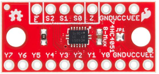
It takes 4 GPIO pins to read or write 8 independent signals. This means that you could have 8 LEDs connected to the board, 8 buttons, 8 single pin sensors, resistor ladders and more.
The pins marked S0, S1, S2 are used to select the pin you want to control. You write the digital values in the table to these pins to select the channel you want to use.
| Pin | S2 | S1 | S0 |
|---|---|---|---|
| Y0 | 0 | 0 | 0 |
| Y1 | 0 | 0 | 1 |
| Y2 | 0 | 1 | 0 |
| Y3 | 0 | 1 | 1 |
| Y4 | 1 | 0 | 0 |
| Y5 | 1 | 0 | 1 |
| Y6 | 1 | 1 | 0 |
| Y7 | 1 | 1 | 1 |
After that, it's a simple matter of reading or writing digital or analog values to the z pin on the board.
This IC isn't the same as a shift register. For a start, you are not limited to digital values and you can input and output on any of the 8 channels. The downside is that the signals you write only go to your devices when that particular pin is selected. Although you can connect LEDs, as in the example on this page, you have to work harder in your program to get the effects you tend to want from LEDs. Where your output signal is a trigger, that would work quite well.
Input, on the other hand, is quite handy. The board works pretty well for reading a bunch of buttons and analog sensors.
Circuit
I started my test circuit by connecting up 4 LEDs and 4 buttons, something like this,
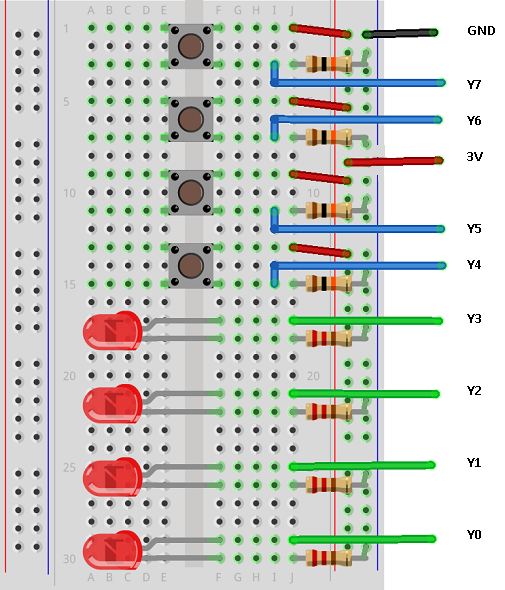
The resistors with the buttons are 10K Ohm resistors, connected to GND. The resistors on the short legs of the LEDs are 220 Ohms.
I actually used 4 LED buttons, connecting to the same pins as in the diagram,
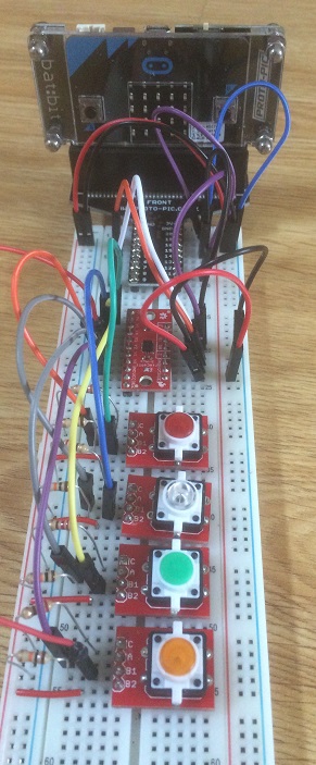
I then connected the VCC and GND pins on the breakout to the micro:bit. Pin 0 on the micro:bit is connected to the Z pin on the breakout. S0 - S2 are connected to pins 8, 12 and 16 on the micro:bit.
Programming
Programming the breakout is all about selecting the pin that you want to control. I wrote a class to do the pin selection and started by making an LED of my choice light up and then respond to one of the buttons being pressed.
The select pins work like binary place values. This is handy from a programming point of view. The number of the pin we want to choose has the pattern of select pins in its binary representation.
from microbit import *

class hc4051:

    def __init__(self, s0pin,s1pin,s2pin,zpin):
        self.pins = [s0pin,s1pin,s2pin]
        self.z = zpin

    def select_pin(self, the_pin):
        for i in range(3):
            self.pins[i].write_digital((the_pin>>i) & 1)

mplex = hc4051(pin8,pin12,pin16,pin0)
# turn on LED on pin2 (3rd) for a second
mplex.select_pin(2)
pin0.write_digital(1)
sleep(1000)
pin0.write_digital(0)

# read button connected to pin 4
mplex.select_pin(4)
while True:
    if pin0.read_digital()==1:
        display.show(Image.YES)
    else:
        display.clear()
    sleep(50)
In this second example, I turned the LEDs on in sequence, using a loop.
from microbit import *

class hc4051:

    def __init__(self, s0pin,s1pin,s2pin,zpin):
        self.pins = [s0pin,s1pin,s2pin]
        self.z = zpin

    def select_pin(self, the_pin):
        for i in range(3):
            self.pins[i].write_digital((the_pin>>i) & 1)


mplex = hc4051(pin8,pin12,pin16,pin0)
# LEDs one at a time - leave z pin HIGH
pin0.write_digital(1)
for i in range(4):
    mplex.select_pin(i)
    sleep(500)
pin0.write_digital(0)
Then I had a play with the buttons, reading them with a loop and building a binary integer to represent the on and off buttons.
from microbit import *

class hc4051:

    def __init__(self, s0pin,s1pin,s2pin,zpin):
        self.pins = [s0pin,s1pin,s2pin]
        self.z = zpin

    def select_pin(self, the_pin):
        for i in range(3):
            self.pins[i].write_digital((the_pin>>i) & 1)

mplex = hc4051(pin8,pin12,pin16,pin0)

while True:
    reading = 0
    for i in range(4,8):
        mplex.select_pin(i)
        reading += pin0.read_digital()<<(i-4)
    print('{:04b}'.format(reading))
    sleep(50)
This last example works best with the LED buttons. The idea was to have the LED lit when the relevant button is pressed.
from microbit import *

class hc4051:

    def __init__(self, s0pin,s1pin,s2pin,zpin):
        self.pins = [s0pin,s1pin,s2pin]
        self.z = zpin

    def select_pin(self, the_pin):
        for i in range(3):
            self.pins[i].write_digital((the_pin>>i) & 1)

mplex = hc4051(pin8,pin12,pin16,pin0)

while True:
    reading = 0
    for i in range(4):
        mplex.select_pin(i+4)
        reading += pin0.read_digital()<<i
    for i in range(4):
        mplex.select_pin(i)
        pin0.write_digital((reading>>i)&1)
        sleep(5)
        pin0.write_digital(0)
What Next?
There are some additions to the class that would help with future programming. Getting 8 digital readings and receiving it as a byte would be useful for connecting 8 buttons or switches to the board. When reading a group of buttons in a loop, you can use the byte to quickly check for a change of state rather than track each input individually.
You can have more than one LED on at a time as long as you run your program with minimal delays. As long as you switch pretty quickly between the select pins, you create the impression that the LED is remaining on. Having a method that can write 8 output signals from a byte, with an adjustable delay between each, would allow for some LED effects. You could control a 7 segment character display if you are crafty.
Similarly, it would be useful to have a method that read 8 analog inputs and returned them as a handy list.
Then it's all about the applications. The board appears to be most useful when it comes to inputs - components where you want to read a signal every now and then. Sparkfun have an example for Arduino with 8 photocells. It would be interesting to use the same circuit for detecting gestures. 8 in a row is not necessarily optimal for this (grid?), but would be the easiest on a breadboard and still gives scope for detecting a handful of approaches.
There are infrared analog line sensors that have 8 sensors. They take up some juice but would give super accurate readings and would provide the basis for the most flexible and adaptable line sensing on a robot vehicle.
The VKey voltage keyboard gave 12 inputs on a single analog signal. My DIY version used 5 buttons and the resistors I had. Either way, a resistor ladder of some sort on each of the input channels gives the possiblity of a huge number of controllable 'digital' inputs via the analog signals.
Being able to reuse the same pin means being able to use that pin's features. Using one of the touch pins like this should allow use of the built-in touch method on the pin, meaning a handful of extra touch inputs.