BBC Microbit
![]()


BBC micro:bit
PiRTC PCF8523 Real Time Clock
Introduction
The PiRTC is a Raspberry Pi accessory made by Adafruit. It is a real time clock breakout board that is meant to attach to the Raspberry Pi's GPIO to keep time. It is a tiny little board and the time-keeping is accurate to a few seconds a day.
I connected the board up with a 4tronix Bit:2:Pi and a Pimoroni pHAT Stack.
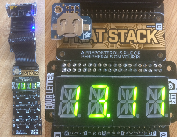
The extras here are overkill for this project. The Bit:2:Pi is a useful bridge for working with pHATs and HATs and SHIMs. It provides the power for any 5V parts and makes it easy to connect the board. Since I also wanted to use the Four Letter pHAT with this, I went for the Pimoroni pHAT stack. The pHAT stack is a glorious and preposterous piece of kit which leaves me 3 more 40 pin GPIO headers for add-ons.
Circuit
The setup shown in the photograph is the easiest way to get this working. Alternatively, you can connect the devices up with jumper cables in the headers. For the PiRTC, you will need to connect 3V3, SDA, SCL and GND headers of the PiRTC to their respective i2c and power pins on the micro:bit. That means SDA to 20, SCL to 19.
The Four Letter pHAT, needs the same connections (the devices have different addresses) but also needs the 5V connection to be made to a power source. On the Bit:2:Pi, I power it with the 3xAA batteries without problems.
Programming
The time needs to be set on the RTC and a quick test is needed.
from microbit import *

def bcd2bin(value):
    return (value or 0) - 6 * ((value or 0) >> 4)

def bin2bcd(value):
    return (value or 0) + 6 * ((value or 0) // 10)

def get_time():
    i2c.write(0x68, b'\x03')
    buf = i2c.read(0x68, 7)
    s = bcd2bin(buf[0] & 0x3F)
    m = bcd2bin(buf[1])
    h = bcd2bin(buf[2])
    dd = bcd2bin(buf[3])
    w = bcd2bin(buf[4])
    mm = bcd2bin(buf[5])
    yy = bcd2bin(buf[6]) + 2000
    return s,m,h,w,dd,mm,yy

def set_time(s,m,h,w,dd,mm,yy):
    tm = [0x03] + [bin2bcd(i) for i in [s,m,h,w,dd,mm,yy-2000]]
    i2c.write(0x68,bytes(tm))

#set_time(0,49,12,25,2,10,2017)

while True:
    print(get_time())
    sleep(1000)
There are minor differences between the way that this RTC stores its data compared with other ones likes the DS3231 or the DS1307. The datasheet is needed to let you know the order of the registers and the binary formats used.
With the Four Letter pHAT connected, I wanted to view the time nicely displayed. This code did the job, although a tidy-up is needed.
from microbit import *

class FourLetter:
    ADDRESS             = 0x70
    BLINK_CMD           = 0x80
    CMD_BRIGHTNESS      = 0xE0
    font = [0x0,0x6,0x220,0x12ce,0x12ed,0xc24,0x235d,0x400,0x2400,0x900,
        0x3fc0,0x12c0,0x800,0xc0,0x0,0xc00,0xc3f,0x6,0xdb,0x8f,0xe6,
        0x2069,0xfd,0x7,0xff,0xef,0x1200,0xa00,0x2400,0xc8,0x900,
        0x1083,0x2bb,0xf7,0x128f,0x39,0x120f,0xf9,0x71,0xbd,0xf6,
        0x1200,0x1e,0x2470,0x38,0x536,0x2136,0x3f,0xf3,0x203f,0x20f3,
        0xed,0x1201,0x3e,0xc30,0x2836,0x2d00,0x1500,0xc09,0x39,0x2100,
        0xf,0xc03,0x8,0x100,0x1058,0x2078,0xd8,0x88e,0x858,0x71,0x48e,
        0x1070,0x1000,0xe,0x3600,0x30,0x10d4,0x1050,0xdc,0x170,0x486,
        0x50,0x2088,0x78,0x1c,0x2004,0x2814,0x28c0,0x200c,0x848,0x949,
        0x1200,0x2489,0x520]

    def __init__(self):
        self.buffer = bytearray([0]*16)
        i2c.write(self.ADDRESS,b'\x21',repeat=False)
        self.blink_rate(0)
        self.set_brightness(15)
        self.update_display()

    def write_reg(self,reg,value):
        i2c.write(self.ADDRESS, bytes([reg,value]), repeat=False)

    def blink_rate(self, b):
        if b>3:
            b=0
        i2c.write(self.ADDRESS,bytes([self.BLINK_CMD | 1 | (b << 1)]), repeat=False)

    def set_brightness(self,b):
        if b>15:
            b=15
        i2c.write(self.ADDRESS,bytes([self.CMD_BRIGHTNESS | b]), repeat=False)

    def update_display(self):
        data = bytearray([0]) + self.buffer
        i2c.write(self.ADDRESS,data,repeat=False)

    def clear(self):
        self.buffer = bytearray([0]*16)

    def raw_digit(self, value, position):
        self.buffer[position*2]   = value & 0xFF
        self.buffer[position*2+1] = (value >> 8) & 0xFF

    def set_digit(self, value, position):
        self.raw_digit(self.font[ord(value)-32], position)

    def print_str(self, value, ralign=True):
        # Calculate starting position of digits
        pos = (4-len(value)) if ralign else 0
        for i, ch in enumerate(value):
            self.set_digit(ch,i+pos)

    def set_decimal(self, decimal, pos):
        if pos < 0 or pos > 3:
            return
        # Set bit 14
        if decimal:
            self.buffer[pos*2+1] |= (1 << 6)
        else:
            self.buffer[pos*2+1] &= ~(1 << 6)

def bcd2bin(value):
    return (value or 0) - 6 * ((value or 0) >> 4)

def bin2bcd(value):
    return (value or 0) + 6 * ((value or 0) // 10)

def get_time():
    i2c.write(0x68, b'\x03')
    buf = i2c.read(0x68, 7)
    s = bcd2bin(buf[0] & 0x3F)
    m = bcd2bin(buf[1])
    h = bcd2bin(buf[2])
    dd = bcd2bin(buf[3])
    w = bcd2bin(buf[4])
    mm = bcd2bin(buf[5])
    yy = bcd2bin(buf[6]) + 2000
    return s,m,h,w,dd,mm,yy

flh = FourLetter()
while True:
    s,m,h,w,dd,mm,yy = get_time()
    hrs = str(h)
    if h<10: hrs = "0"+hrs
    mins = str(m)
    if m<10: mins = "0"+mins
    flh.print_str(hrs + mins)
    flh.set_decimal(1,1)
    flh.update_display()
    sleep(60000)
Reflections
The RTC is nice and easy to work with and will fit neatly into future projects. The project needs some features to make it live a little. There's plenty of space on the pHAT Stack for some extra boards. Before that though, the code needs to be trimmed down a lot.
The Bit:2:Pi and pHAT Stack were unnecessary for this project but made it so much easier. I placed 2 jumpers on the Bit:2:Pi to connect the i2c pins of the micro:bit to the right part of the Pi GPIO headers. The power is taken care of. Although it might seem a little much if you just want to try out one pHAT on the micro:bit, it works nicely as an general purpose edge connector too. The pHAT stack allowed me to connect two accessories easily and left space for more kit and connections.
The next step is to add a user interface, one of the touch-input Pi accessories, probably. After that, a buzzer is going to be needed for alarms. Something blinky to finish the whole thing off and the clock will have many features, like date display and stopwatch functionality.