BBC Microbit
![]()


BBC micro:bit
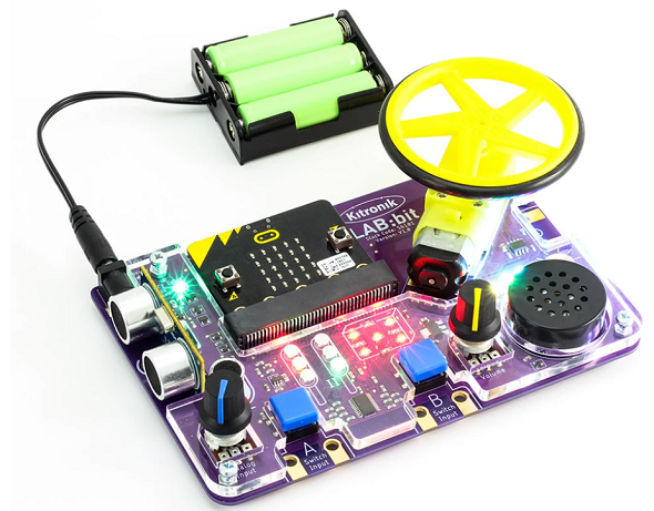
Kitronik LAB:bit
Introduction
The LAB:bit is made by Kitronik. It is billed as an all-in-one laboratory for younger students to learn about programming and electronic components. The board has an impressive array of components,
- Ultrasound Distance Sensor
- Motor
- Potentiometer
- Microphone
- 7 Neopixels
- Speaker - volume adjustable by potentiometer
- Pushbuttons connected to the A & B buttons of the micro:bit
- 2 sets of red, yellow and green LEDs intended for use as traffic lights
- 9 LEDs arranged so as to be usable for showing dice rolls.
The traffic light and dice LEDs are connected via an i2c port expander.
The board has an edge connector for inserting your micro:bit, version 1 or 2, and needs an external power supply. A 3xAA battery holder comes with the product.
There is a MakeCode library that can be used with the LAB:bit. It is well written, has tutorials and looks great for young learners. I couldn't find any published MicroPython when I wrote this page and thought I'd have a go at hacking together some code to interact with the components. I'm going to include just about enough code to get things working and leave the experimentation and refining of the code to you. I'm also going to deal with each of the components separately.
Ultrasonic Distance Sensor
The distance sensor is an HC-SR04. With distance sensors like this, you have a trigger pin. Toggling the trigger causes the sensor to send out an ultrasonic pulse which you detect on the echo pin. In this setup, the trigger pin is pin13 and the echo pin is pin15. Using code from a previous project, I went with,
from microbit import *
import machine
import utime

def get_dist():
    pin13.write_digital(0)
    utime.sleep_us(2)
    pin13.write_digital(1)
    utime.sleep_us(10)
    pin13.write_digital(0)
    d = machine.time_pulse_us(pin15,1,11600)
    if d>0:
        return d/58
    else:
        return d

pin15.set_pull(pin15.NO_PULL)
while True:
    if button_a.was_pressed():
        d = get_dist()
        display.scroll(d)
        sleep(150)
    sleep(20)
Potentiometer
The potentiometer that you can read is connected to pin2. I can get readings from 3 to 1023 from it. The following is very simple code to show the reading whenever the A button is pressed.
from microbit import *

while True:
    if button_a.was_pressed():
        reading = pin2.read_analog()
        display.show(reading)
        sleep(150)
    sleep(20)
Neopixels
The 7 Neopixels are connected to pin8 on the micro:bit. There is plenty of Neopixel code dotted around this site that you can use, but here is a quick test to see things working on the LAB:bit.
from microbit import *
import neopixel

def lightall(c):
    for p in range(len(np)):
        np[p] = c
    np.show()

np = neopixel.NeoPixel(pin8,7)
red = (255,0,0)
green = (0,255,0)
blue = (0,0,255)
off = (0,0,0)

while True:
    lightall(red)
    sleep(1000)
    lightall(green)
    sleep(1000)
    lightall(blue)
    sleep(1000)
    lightall(off)
    sleep(1000)
Microphone
The microphone is connected to pin1. I took code that Pimoroni wrote for their enviro:bit and combined it with some Neopixel code to make a program that turns the neopixels on and off when you double clap. The sensitivity might need a little tweak but this is near enough to give the idea.
from microbit import *
import neopixel

def lightall(c):
    for p in range(len(np)):
        np[p] = c
    np.show()

def read():
    return max(0, pin1.read_analog() - offset)

def wait_for_double_clap(timeout=1000, spread=500, sensitivity=75):
    sensitivity = 105 - sensitivity
    clap_one_time = None
    start_time = running_time()
    while running_time() - start_time < timeout:
        if read() > sensitivity:
            while read() > sensitivity:
                pass
            sleep(100)
            if clap_one_time is not None and running_time() - clap_one_time < spread:
                return True
            else:
                clap_one_time = running_time()
    return False

on = False
np = neopixel.NeoPixel(pin8,7)
red = (255,0,0)
off = (0,0,0)
offset = 580
while True:
    q = wait_for_double_clap()
    if(q):
        if(on):
            lightall(off)
            on = False
        else:
            lightall(red)
            on = True
Motor
The motor driver chip is a TC118S which can drive a single motor. It takes 2 inputs. You drive one of them low and use PWM on the other one to set the speed. The following program allows you to set the motor speed and direction using positive or negative values from -1023 to +1023.
from microbit import *

def drive(x):
    if x<0:
        x = abs(x)
        pin12.write_analog(x)
        pin16.write_digital(0)
    else:
        pin16.write_analog(x)
        pin12.write_digital(0)

while True:
    if button_a.was_pressed():
        drive(1023)
        sleep(1000)
        drive(0)
    elif button_b.was_pressed():
        drive(-1023)
        sleep(1000)
        drive(0)
    sleep(10)
The Traffic Lights
To use the traffic lights, we need to work with the port expander. The port expander is a PCA9555 i2c chip that provides 16 GPIO pins.
We use two bytes to control the LEDs. By setting bits to 0, we can turn individual LEDs on and off. In the following program, I have added code to invert that logic so that you can use a 1 for on and a 0 for off.
from microbit import *

t = [0,0,0,0,0,0]
a  = 255
b = 255

def gpio_init():
    i2c.write(0x23,b'\x06\x00\x00')
    sleep(1)
    i2c.write(0x23,b'\x02\xFF\xFF')
    sleep(1)

def readout():
    buf = i2c.read(0x23,2)
    return buf[0], buf[1]

def update():
    i2c.write(0x23,bytes([0x02,a,b]))

def setbit(n,p,v):
    if v:
        return n & (~(1<<p))
    else:
        return n | (1<<p)

def traffic():
    global a,t
    for i in range(6):
        a = setbit(a,i,t[i])

gpio_init()

while True:
    for i in range(6):
        t[i] = 1
        traffic()
        update()
        c, d = readout()
        print(bin(c))
        sleep(1000)
        t[i] = 0
        traffic()
        update()
The list t is used to store the states of the LEDs. In order, the numbers represent the red, yellow and green LEDs of the first set of lights, followed by the second set in the same order. To control the lights in this program, change elements in the list. Then call the traffic() procedure to change byte a. Then call the update() procedure to write the changes to the port expander.
In the test code at the end, I have turned each LED on, one at a time. The readout() function gets the state of the two pin control registers and prints it so that you can read it in the REPL window.
The Dice
Using dot patterns on the dice is pretty easy because you only need to use LEDs that are controlled with the second byte. By writing this byte with the correct bit pattern, you can get the dots you want onto the dice. In the following script, the dots are put onto the dice by setting the variable b to the right item from the list and then updating the port expander like before.
from microbit import *

a  = 255
b = 255

dots = [0xFF,0xF7,0xEB,0xE3,0xAA,0xA2,0x88]

def gpio_init():
    i2c.write(0x23,b'\x06\x00\x00')
    sleep(1)
    i2c.write(0x23,b'\x02\xFF\xFF')
    sleep(1)

def update():
    i2c.write(0x23,bytes([0x02,a,b]))

gpio_init()

while True:
    for i in range(1,7):
        b = dots[i]
        update()
        sleep(1000)
        b = 255
        update()
        sleep(1000)
The MakeCode library includes the ability to write the digits 0 to 9 on the LEDs. I was not overly impressed with the effect so have not included the code on this page. You might have a go yourself if you are up for the challenge.