BBC Microbit
![]()


BBC micro:bit
PS3 Dualshock Controller
Introduction
A while ago I was looking for a way to control an Arduino robot car and really wanted the number of options and ergonomics that you get from a console game controller. I came across the USB host controller from Hobbytronics with the option for a PS3 controller. The board is meant to be used to connect a wired controller. The cost of PS3 controllers led me to look for a cheap third party controller and I came across a controller called Speedlink Strike Fx which was a rechargeable wireless controller with a little stick to go in the USB socket. Since the wireless Sony ones were using bluetooth, I reasoned that the stick must be generating the USB signals that a wired controller would and that it would be worth a go. It worked a treat on the 5V Arduino it was aimed at.
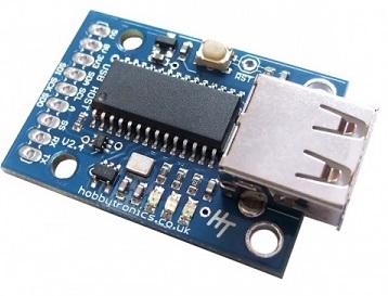
The board is advertised as working at 3V3 and uses i2c to feed you the readings from the PS3 controller. It was worth a go on the micro:bit and it turns out it works quite nicely. Using a cheap controller means that my buttons are not pressure-sensitive. It also means that any analog readings are not really usable as anything more than switches. I also don't have the accelerometer. Even without that, I have more than a dozen inputs and wireless.
Connections
This is an i2c connection. That means micro:bit pins 20 and 19 go to SDA and SCL. Connect the micro:bit 3V to the USB Host board's 5V pin (this is VCC for the board) and connect GND to the pin marked 0V.
Programming
There are 35 things to read on a PS3 controller and, using the i2c protocol, we receive each one of them as a byte. They come in this order,
| Byte | Input |
|---|---|
| 0 | left_joystick_x |
| 1 | left_joystick_y |
| 2 | right_joystick_x |
| 3 | right_joystick_y |
| 4 | accelerometer_x |
| 5 | accelerometer_y |
| 6 | pressure_up |
| 7 | pressure_right |
| 8 | pressure_down |
| 9 | pressure_left |
| 10 | pressure_lb |
| 11 | pressure_rb |
| 12 | pressure_lt |
| 13 | pressure_rt |
| 14 | pressure_triangle |
| 15 | pressure_circle |
| 16 | pressure_x |
| 17 | pressure_square |
| 18 | button_left |
| 19 | button_down |
| 20 | button_right |
| 21 | button_up |
| 22 | button_start |
| 23 | button_right_joystick |
| 24 | button_left_joystick |
| 25 | button_select |
| 26 | button_square |
| 27 | button_x |
| 28 | button_circle |
| 29 | button_triangle |
| 30 | button_rt |
| 31 | button_lt |
| 32 | button_rb |
| 33 | button_lb |
| 34 | button_ps3 |
There are two ways to get the readings in this class. One method returns a list, the other a dictionary with the names of the items from the table as a key. In this version, both are printed and can be seen in the REPL window.
The quirky sequence in the initialisation was something I found was the only way to stop my controller from rumbling when it first detects its receiver. You may not need it. I found that cycling through the lights did the job for me. The joysticks and dpad methods return tuples. You can add your own methods for anything you want to work with in a particular application.
from microbit import *

class ps3:

    def __init__(self):
        self.addr = 41
        self.led_cmd = 51
        # initialisation sequence?
        sleep(500)
        self.ps3_led(0x01)
        sleep(500)
        self.ps3_led(0x02)
        sleep(500)
        self.ps3_led(0x04)
        sleep(500)
        self.ps3_led(0x08)
        sleep(500)
        self.ps3_led(0x01)
        sleep(500)

    # 4 bit number, 0 - 3 bits for LEDs 1 - 4
    def ps3_led(self,a):
        i2c.write(self.addr, bytes([self.led_cmd,a]), repeat=False)

    def readall(self):
        i2c.write(self.addr, b'\x00', repeat=False)
        sleep(1)
        buf = i2c.read(self.addr, 32, repeat=False)
        return buf

    def ps3_joysticks(self):
        buf = self.readall()
        # leftX, leftY, rightX, rightY
        return buf[0],buf[1],buf[2],buf[3]

    def ps3_dpad(self):
        buf = self.readall()
        # left, down, right, up
        return buf[18],buf[19],buf[20],buf[21]

    def ps3_info(self):
        buf = self.readall()
        keys = ["left_joystick_x","left_joystick_y","right_joystick_x",
        "right_joystick_y","accelerometer_x","accelerometer_y","pressure_up",
        "pressure_right","pressure_down","pressure_left","pressure_lb",
        "pressure_rb","pressure_lt","pressure_rt","pressure_triangle",
        "pressure_circle","pressure_x","pressure_square","button_left",
        "button_down","button_right","button_up","button_start","button_right_joystick",
        "button_left_joystick","button_select","button_square","button_x",
        "button_circle","button_triangle","button_rt","button_lt","button_rb",
        "button_lb","button_ps3"]
        return dict(zip(keys,buf))

joy = ps3()

while True:
    # Dictionary
    ps3info = joy.ps3_info()
    # List
    ps3all = joy.readall()
    print("DICT: L ",ps3info['button_left']," R ", ps3info['button_right'],
    " U ", ps3info['button_up']," D ", ps3info['button_down'], "  LIST : L ",
    ps3all[18]," R ", ps3all[20]," U ", ps3all[21]," D ", ps3all[19], sep = '')
    sleep(50)
Here's a simple example responding to D-pad presses and shows another way to test this circuit.
from microbit import *

class ps3:

    def __init__(self):
        self.addr = 41
        self.led_cmd = 51
        # initialisation sequence?
        sleep(500)
        self.ps3_led(0x01)
        sleep(500)
        self.ps3_led(0x02)
        sleep(500)
        self.ps3_led(0x04)
        sleep(500)
        self.ps3_led(0x08)
        sleep(500)
        self.ps3_led(0x01)
        sleep(500)

    # 4 bit number, 0 - 3 bits for LEDs 1 - 4
    def ps3_led(self,a):
        i2c.write(self.addr, bytes([self.led_cmd,a]), repeat=False)

    def readall(self):
        i2c.write(self.addr, b'\x00', repeat=False)
        sleep(1)
        buf = i2c.read(self.addr, 32, repeat=False)
        return buf

    def ps3_dpad(self):
        buf = self.readall()
        # left, down, right, up
        return buf[18]==1,buf[19]==1,buf[20]==1,buf[21]==1

joy = ps3()

while True:
    l,d,r,u = joy.ps3_dpad()
    if l==1 and u==1:
        display.show(Image.ARROW_NW)
    elif l==1 and d==1:
        display.show(Image.ARROW_SW)
    elif r==1 and u==1:
        display.show(Image.ARROW_NE)
    elif r==1 and d==1:
        display.show(Image.ARROW_SE)
    elif u==1:
        display.show(Image.ARROW_N)
    elif d==1:
        display.show(Image.ARROW_S)
    elif l==1:
        display.show(Image.ARROW_W)
    elif r==1:
        display.show(Image.ARROW_E)
    else:
        display.clear()
    sleep(10)
Challenges
- The first challenge is to test all of the functions with the controller that you have. You could use serial output or even create a log file if you look at the section on the file system.
- It's overkill, but using the controller to play a game on the matrix is a fun idea. You can use one of the examples on this site, find another or make your own.
- If you have a robot vehicle, there's not much to say, you need to do it. If your robot platform does not allow you to connect the USB host board to that, you can use it with a second micro:bit and its radio to relay the signal.
- Add a buzzer and map the notes of an octave or some other mellifluous combination onto the controller inputs.
- If you make a MIDI connection to the micro:bit - you can send MIDI messages. See the two pages for different ways to do that, with or without a USB PC connection. You could either set up a full drum kit ergonomically on the controller or create your own combi-instrument. There's an enormous amount that you can do with MIDI - the large range of inputs on a controller give you lots of possibilities.
- Use the controller as a remote control with a set of Neopixels or lots of LEDs.
- Connect up an LCD and work out a way to enter text on the display using the controller.