BBC Microbit
![]()


BBC micro:bit
Rotary Encoder
Introduction
A rotary encoder has a knob to rotate a little bit like a rotary potentiometer. One big difference is that the knob can be rotated continuously. There are two main types of output from a rotary encoder, Gray Code and Quadrature. Both are binary codes to represent data from the encoder. Depending on the type of encoding, a rotary encoder's output could indicate the absolute position of the knob or the amount and direction of a rotation of the encoder by the user.
In this project, we'll be sacrificing buttons A and B by connecting our rotary encoder directly up to them. This simplifies our circuit and means that we can learn a little bit about a simple rotary encoder along the way.
I used a PCB mounting rotary encoder for this that gives 2 bit quadrature output. We can read direction only.
Circuit
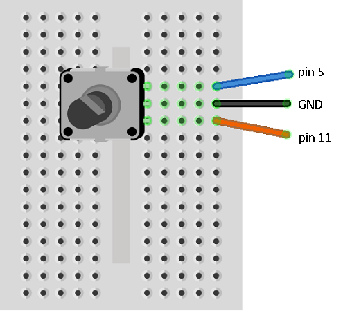
This type of rotary encoder has 3 pins, A, B and GND. We connect GND to the micro:bit GND pin. The other two pins we connect to pins 5 and 11 on the micro:bit. These are the pins that are connected to the micro:bit buttons. These pins are pulled high by internal resistors.
The two pins of the rotary encoder work something like this,
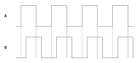
The two waves are out of phase. The dotted red line shows us that, when turning clockwise, and the signal from A changes from high to low, the B signal will be a high. When turning anticlockwise, when A changes from high to low, there is a dotted blue line showing us that the B signal will be low.
Connect the circuit like this,
Program 1
This is our test that we can read the rotary encoder. You should be able to rotate the knob to adjust the number on the display from 0 to 9.
from microbit import *

lastA = False
x = 0
while True:
    a = button_a.is_pressed()
    b = button_b.is_pressed()
    display.show(str(x))
    if not a and lastA:
        if b:
            x = x - 1
        else:
            x = x + 1
    # keep x from 0 to 9
    x = max(0, min(x, 9))
    lastA = a
    sleep(5)
If your numbers don't go in the right direction, either change the code or swap your pin 5 and pin 11 cables over.
Now, the buttons on the micro:bit aren't disabled because we are doing this, they are still connected up. Press the A button to increase the number. Holding down the B button allows you to decrease the number.
Program 2
Combining this with code used to display from 0 to 25 LEDs, we get the next program. You get a sense of how imprecise the encoder is when you go too quickly.
from microbit import *

# function to create an image consisting of value LEDs
def nleds(value):
    img = Image('00000:'*5)
    sp = img.set_pixel
    counter = 0
    for row in range(0,5):
        for col in range(0,5):
            if counter<value:
                sp(col,row,9)
            else:
                sp(col,row,0)
            counter += 1
    return img

lastA = False
x = 0
display.show(nleds(x))
while True:
    a = button_a.is_pressed()
    b = button_b.is_pressed()
    if not a and lastA:
        if b:
            x = x - 1
        else:
            x = x + 1
        x = max(0, min(x, 25))
        display.show(nleds(x))
    lastA = a
    sleep(5)
Program 3
And finally, moving a pixel from left to right.
from microbit import *

lastA = False
x = 2
display.set_pixel(x,4,9)
while True:
    a = button_a.is_pressed()
    b = button_b.is_pressed()
    if not a and lastA:
        display.set_pixel(x,4,0)
        if b:
            x = x - 1
        else:
            x = x + 1
        x = max(0, min(x, 4))
        display.set_pixel(x,4,9)
    lastA = a
    sleep(5)
Challenge
Use the rotary encoder as the input in any of the projects where you relied on single presses of the A and B buttons.