BBC Microbit
![]()


BBC micro:bit
IS31FL3731 Digital Clock
Introduction
This project came about when I was experimenting with the Adafruit Charlieplexed 16x9 matrix. It's based on something I did on an Arduino with the Lolshield. The Adafruit board has a few more LEDs and makes for a nicer way to display the time.
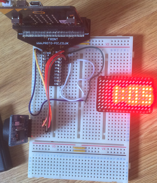
The image shows the time being displayed on the matrix. 4 digits can be displayed, but not with a leading zero under my scheme.
Circuit
This is the simplest part of the idea. Both devices connect to i2c. They have different addresses and can share the same connection. There's nothing fancy.
Connect the VCC of each board to 3V, connect the GNDs to GND. The SDAs go to pin 20 and the SCLs to pin 19. That's it.
Programming
When I started on this, I quickly found how inefficient my code was for the Adafruit display. Instead of writing it better than I had, I just hacked about a bit and swapped function calls for code to do the same job.
The next problem was how to define a 'font' for the numeric digits. I went for the same approach I'd done before and designed them to be 3x5 in size, like this,
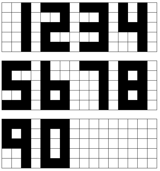
These 'characters' could be displayed on the matrix like this,
This spacing means that 1 is the only digit that can be displayed first. In a 12 hr clock, that isn't a problem.
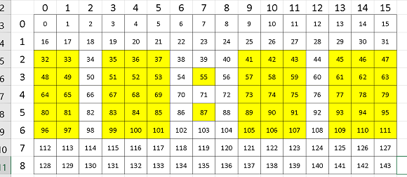
Then I needed a way to represent it. I went for the simplest, but least efficient way to do this by using the denary values of the LEDs that would be on if the digit were in the top left of the matrix. This gave me the list of lists called DIGITS.
from microbit import *

class Matrix:
    DIGITS = [
            [0,1,2,16,18,32,34,48,50,64,65,66],
            [2,18,34,50,66],
            [0,1,2,18,32,33,34,48,64,65,66],
            [0,1,2,18,32,33,34,50,64,65,66],
            [0,2,16,18,32,33,34,50,66],
            [0,1,2,16,32,33,34,50,64,65,66],
            [0,1,2,16,32,33,34,48,50,64,65,66],
            [0,1,2,18,32,33,34,50,64,65,66],
            [0,1,2,16,18,32,33,34,48,50,64,65,66],
            [0,1,2,16,18,32,33,34,50,64,65,66]
            ]
    def __init__(self):
        # off an on again
        self.write_reg8(0x0b, 0x0a,0x0)
        sleep(10)
        self.write_reg8(0x0b, 0x0a,0x1)
        # select picture mode
        self.write_reg8(0x0b, 0, 0)
        self.write_reg8(0x0b, 0x01, 0)
        self.fill(0)
        for f in range(8):
            for i in range(18):
                self.write_reg8(f,i,0xff)
        # turn off audio sync
        self.write_reg8(0x0b,0x06, 0x0)

    def fill(self, value):
        self.select_bank(0)
        for i in range(6):
            d = bytearray([0x24 + i * 24]) + bytearray(([value]*24))
            i2c.write(0x74, d, repeat=False)

    def select_bank(self, bank):
        self.write_reg(0xfd, bank)

    def write_reg(self,reg,value):
        i2c.write(0x74, bytes([reg,value]), repeat=False)

    def write_reg8(self,bank, reg, value):
        self.select_bank(bank)
        self.write_reg(reg, value)

    def set_led_pwm(self, lednum, frame, value):
        self.write_reg8(frame, 0x24 + lednum, value)

    def display_digit(self,d,x):
        for l in self.DIGITS[d]:
            self.write_reg8(0,0x24+l+x,255)


# RTC functions
def bcd2dec(bcd):
    return (((bcd & 0xf0) >> 4) * 10 + (bcd & 0x0f))

def dec2bcd(dec):
    tens, units = divmod(dec, 10)
    return (tens << 4) + units

def get_time():
    i2c.write(addr, b'\x00', repeat=False)
    buf = i2c.read(addr, 7, repeat=False)
    ss = bcd2dec(buf[0])
    mm = bcd2dec(buf[1])
    if buf[2] & 0x40:
        hh = bcd2dec(buf[2] & 0x1f)
        if buf[2] & 0x20:
            hh += 12
    else:
        hh = bcd2dec(buf[2])
    wday = buf[3]
    DD = bcd2dec(buf[4])
    MM = bcd2dec(buf[5] & 0x1f)
    YY = bcd2dec(buf[6])+2000
    return hh,mm,ss,YY,MM,DD,wday

addr = 0x68
buf = bytearray(7)
a = Matrix()
while True:
    hh,mm,ss,YY,MM,DD,wday = get_time()
    a.fill(0)
    if hh>12:
        hh = hh - 12
    if hh>9:
        a.display_digit(1,31)
    hh = hh % 10
    a.display_digit(hh,35)
    a.set_led_pwm(55,0,255)
    a.set_led_pwm(87,0,255)
    q, r = divmod(mm,10)
    a.display_digit(q,41)
    a.display_digit(r,45)
    sleep(60000)
The display_digit method allows us to draw a digit at a particular position on the matrix.
The long sleep could be reduced. The display is being refreshed as it is, you need to think about how much filcker you want and the level of precision you are looking for.
Challenges
- One thing to consider is changing the display code to show whether the time shown is am or pm. There are 2 rows of LEDs that could show this, perhaps with a row at the top for am and one at the bottom for pm.
- Go for a less conventional clock face and you can fit in 4 digits and 24 hour time.
- Since you can make a 5x5 clock face on the micro:bit matrix, you could do 3 side-by-side here to display hours, minutes and seconds.
- The code isn't particularly well optimised here. The class could do with adapting and flattening where possible. The main loop causes an update of all of the digits. If you were wanting to show seconds, why update a digit that will need to be the same for an hour or more? To have time checks every second, you would want to remove the statement that clears the display by filling 0.
- The code for diplaying the digits could be used without the RTC, perhaps to make a stopwatch based on micro:bit time, a scoreboard for a game you are playing, or something else entirely. Shift the colon out of the image and you can easily do 4 plain digits.