BBC Microbit
![]()


BBC micro:bit
Pedestrian Crossing
Introduction
This project simulates some of the traffic lights involved in a pedestrian crossing.
For my version, I used the Pi-Stop, which was designed for use with Raspberry Pi GPIO ports. It is meant for 3V logic and is nice and compact with resistors built into the package. Standard LEDs are fine for this too.

I've set up my simulation with 3 sets of lights. 2 of these sets will be for the cars. The third set is for one direction of the pedestrian crossing. That makes 8 LEDs. A shift register is a good way to leave some GPIO free to add more features to the project later.
Circuit
To get the principle understood and a prototype built, this is set up on a single breadboard. That makes it the same circuit as our shift register with 8 LEDs. The only difference is the choice of colours and a little bit of spacing out.
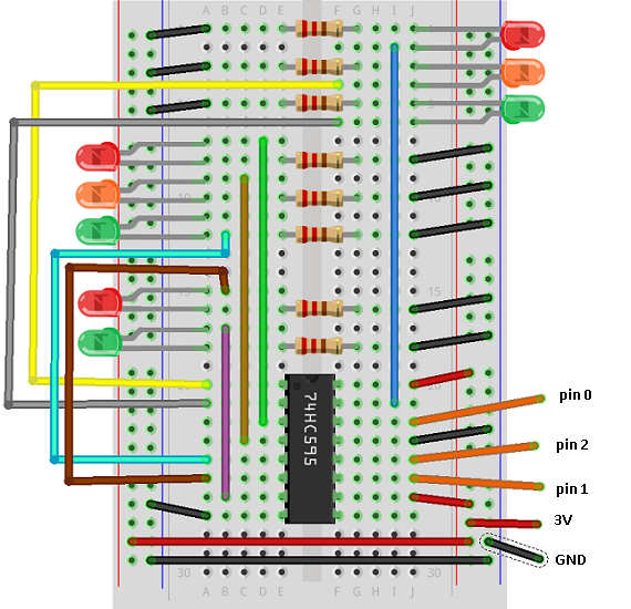
Diagrams with shift registers always look a little confusing. The other page in this section explains more of the principles and has some text that explains the connections.
Program
We can use binary notation to describe the patterns of lights. This program has a ShiftOut() function to make the process a little easier. The timings are just to give a sense of the process. You can look up the true timings if you want to aim for a hyper-realistic simulation.
The ShiftOut function is a useful general purpose function that you can use with this shift register whenever you want. The statements are executed as quickly as the micro:bit can execute Python statements. That doesn't seem to threaten the limits of the integrated circuit, which correctly notices the changes in pin states.
from microbit import *

def ShiftOut(value):
    pin0.write_digital(0)
    pin1.write_digital(0)
    pin2.write_digital(0)
    bits = [value >> i & 1 for i in range(7,-1,-1)]
    for i in range(7,-1,-1):
        pin0.write_digital(bits[i])
        pin1.write_digital(1)
        pin1.write_digital(0)
    pin2.write_digital(1)
    pin2.write_digital(0)

def NoWalk():
    ShiftOut(0b00100110)

def FlashAmber():
    for i in range(0,9):
        ShiftOut(0b01001010)
        sleep(250)
        ShiftOut(0b00000010)
        sleep(250)

def AmberGambler():
    ShiftOut(0b01001010)

def Walk():
    ShiftOut(0b10010001)

def FlashGreen():
    for i in range(0,9):
        ShiftOut(0b10010001)
        sleep(250)
        ShiftOut(0b10010000)
        sleep(250)

NoWalk()
while True:
    if button_a.is_pressed():
        display.show(Image.NO)
        sleep(3000)
        AmberGambler()
        sleep(3000)
        display.show(Image.YES)
        Walk()
        sleep(3000)
        FlashGreen()
        FlashAmber()
        NoWalk()
        display.clear()
Check that you can follow how the binary patterns relate to which LEDs are on or off at any one time.
Challenges
- Obviously, there is a set of lights missing. You could add those. You can use GPIO for this or read about how to chain two of these shift registers together.
- Move the pin 0 connection to another GPIO pin and add a buzzer. Play some appropriate beeps in the same style as the real thing.
- Hunt down the toys that could be used to bring this scene to life. Get hacking.
- Forget about traffics, it's mini disco light time.