BBC Microbit
![]()


BBC micro:bit
Using Components With MicroPython
Introduction
Everything on the Getting Started page applies irrespective of the approach you take to coding. MicroPython has all of the same functionality as the standard code editors with some extra functionality to boot.
A copy of the pinning diagram is included here to be within easy click range of the other links in this section.
Pinning Diagram
Here is a large diagram of the edge connections with labels to show what each one represents.
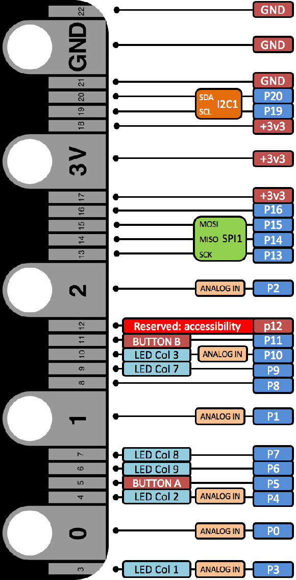
The diagram can be a little confusing if you are new to working with microcontrollers. Let's try to make sense of some of that information.
Pins 5 and 11 are connected to the two buttons on the micro:bit. This allows you to register or trigger a button press using an external component. You could connect a different (larger/better) button to the one of these pins and GND. When the button is pressed, the voltage on the pin goes to 0. This suggests that internal pull-up resistors are used on these pins to pull the digital signal high when the switch is open. This is the normal way to work with switches. Even though it seems odd to get a high signal when the switch is closed (ie circuit is complete), this tends to provide a more reliable way to read the button and avoids an effect with switches that is called bouncing.
Some of the pins are labelled to show that they are being used for the LED matrix. It will be possible to connect to those pins if the matrix is not being used for the program. Otherwise, they need to be avoided.
Power
3V3 is the way that 3.3 volts is normally written. It is written this way so that the decimal point cannot be missed in small print. All of these connections are the positive power connection you make when you connect a component. GND is short for ground. This is our 0 volt or negative connection when we want to connect things. Connecting these two things together is a bad thing - it causes a short circuit and might damage the board.
Analog & Digital
Electronic components rely on either digital or analogue signals. A digital signal means that the input to or output from the component is either 3V3 or 0V. Digital information is like a bit in binary - it can be one of only two values. Pushbuttons or switches are good examples of digital inputs. The button is either being pressed or it is not. There is no in between for these two states.
Analogue components accept input or produce output consisting of a range of voltages from 0V to 3V3. The microcontroller contains an ADC (Analogue to Digital Converter) to convert these analogue signals into a value that can be used by the microcontroller. The micro:bit has a 10 bit ADC so it converts analogue input into a value in the range 0 - 1023. Potentiometers and light sensors are good examples of components that rely on analogue signals.
More Terminology
Pins 19 and 20 are labelled I2C1. These two pins are used to connect devices to the microcontroller using a protocol called inter-integrated circuit or i2c. Whilst you will be able to connect on these lines when the code editors and libraries have been developed further, it is useful to know that the accelerometer and compass on the board are already connected on these pins.
Pins 13 - 16 are used for the SPI or Serial Parallel Interface. This is another standard for communication between electronic devices and is often used for communicating with sensors or displays.
In Summary
You can connect analogue components to pins 0, 1 and 2. You can connect digital components to any of these as well as using pins 8, 12 and 16. That gives you 6 ways to connect to the microcontroller without any effect on the built-in components.