BBC Microbit
![]()


BBC micro:bit
Potentiometer
Introduction
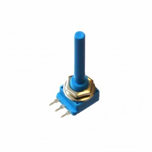
A potentiometer usually comes with 3 pins and is a special type of resistor. By rotating the knob of the potentiometer, you can vary the amount of resistance. You connect the outer two pins to 3V and to GND respectively, you connect the middle pin to one of the analog pins on the micro:bit.
There are all sorts of shapes and sizes for potentiometers. Tiny ones, called trimmer potentiometers will be a bit difficult to connect if you are not using a breadboard. If you are using crocodile/alligator clips to connect your components, a large one might prove easier to connect. I tested the script on this page with one of these linear 10K potentiometers, which cost around 60p to buy.
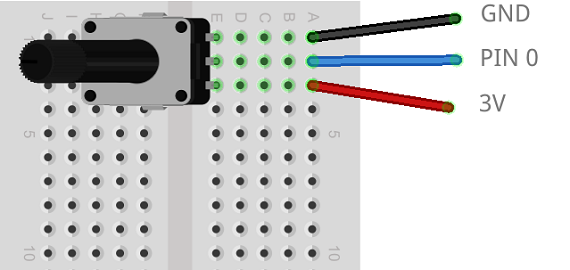
Making The Circuit
You can swap around the 3V and GND pins if you like. It will only change the direction you turn to increase the resistance.
Programming
This small script displays the reading from the potentiometer when button A on the micro:bit is pressed.
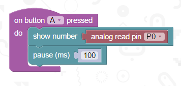
Connected correctly, you should be able to change the number displayed from 0 to 1023. Don't expect it to be accurate to the exact number - you may find you can't quite make it show a 0, but it will not be too far away.
Challenges
- The potentiometer will give you a reading from 0 - 1023. If you divide that number by 4, you can use the reading to set the brightness of the LED matrix.
- You could draw a series of images. Turning the potentiometer could then allow the user to select or scroll through the images displayed on the LED matrix.
- Use some IF statements or the MAP block to convert your potentiometer reading into a number that you can use to move a sprite across one axis of the matrix. Add a second potentiometer and you have both directions.
- A potentiometer and buzzer can be used. Convert the potentiometer reading into a number that you can use to play a tone on the buzzer. Mix in some button action if you want to be able stop and start the buzzing freely.