BBC Microbit
![]()


BBC micro:bit
Using A NOT Gate
Introduction
A NOT gate is one of the fundamental logic circuits used in processors and circuits to perform logical operations. A logical operation is one that results in a HIGH or LOW voltage signal. The NOT gate is sometimes referred to as an inverter. If the signal that enters the gate is HIGH, then a LOW signal leaves. A LOW signal entering the gate results in the output of a HIGH signal.
I use NOT gates in circuits with microcontrollers when I want to invert a signal using components rather than lines of code in my program. Sometimes this is just for the sake of convenience, sometimes it is to speed up processing if the program is complex. Using a NOT gate can be useful if the signal needs to go to other components rather than to the microcontroller. The main reason for using a NOT gate is to reduce the number of GPIO pins needed to control a circuit.
This project is an alternative way to control bi-colour and tri-colour LEDs, halving the number of GPIO pins required for the circuit. The NOT gate used here is the 74HCT04. It is an integrated circuit that includes 6 separate NOT gates and costs less than 50p to buy.
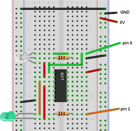
Circuit
The following circuit includes a bi-colour and a tri-colour LED, both connected to the NOT gate. Normally, we would need 2 digital pins for each LED. This circuit removes the need for that but does mean that one of the LEDs will always be on.
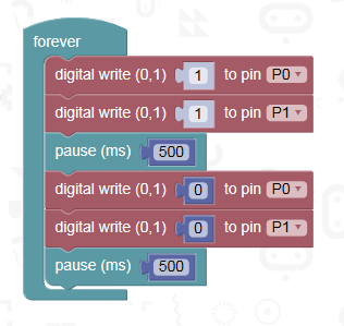
Programming
This is a simple test program to show that the circuit works. The LEDs should alternate their colours.
Challenge
Integrate this circuit and program into a suitable project.