BBC Microbit
![]()


BBC micro:bit
DIY Robot Vehicle
Introduction
If you were looking for an easy route to a decent robot vehicle, you probably don't want to take this approach. There are some nice kits for sale that deal with the motor control and power management that makes it tricky to DIY. For ready-made solutions, the Bit:bot, as described in these pages, is hard to beat for price and features. If the end-product is what it's all about for you, you are not going to be able to match this for price. The company who make this (4tronix) also do a motor driver board that takes the hard work out of the electronics of the motor control. This board, called Robot:bit is used in another 2WD vehicle the company sell and is a really good product too.
The aim of the project was to make a robot vehicle where there is as much choice as possible about which and how many pins are used for motor control. Here were some of the criteria.
- Lowish Cost*
- No more than 4 pins taken up with motor control.
- PWM motor control to vary speed.
- Battery power for motors and micro:bit.
- Choice of pins used for motor control.
- All pins accessible, including matrix pins.
* It costs more to do this step-by-step than it does to pick up ready-made solutions. You don't get the same economies of scale when buying one of each part yourself. The aim is to keep to around £20 with a couple of spare parts taken from old projects.
The ability to turn off the matrix and reclaim its pins for GPIO is one of the advantages of the approach.
Motor Control
The first consideration is working out a suitable motor driver. Motors need more current than you can feed from a micro:bit. They also need to have current flowing in alternate directions - this needs a special circuit called an H-bridge. The simplest way to get this part is to get a cheap motor driver board.
This board has the same component used in the Bit:bot. It only needs 4 pins. It is the Adafruit DRV8833 breakout - there are other versions available for sale.
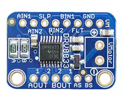
Ideally, you'd use 4 PWM pins to make for slightly easier coding. The 2 PWM approach is the one that saves the pins for us and gives us enough control. It is also happy with 3V3 logic.
Battery Power
This is the tricky part. Ideally, we want to use the same power supply for the micro:bit and the motors. We can't power the motors from the micro:bit directly - the power for the driver board has to come directly from the batteries.
Motors in the cheap chassis kits tend to be best at 4.5V - 6V and we need a clean 3V supply for the micro:bit.
Somehow, we need to split the power input into two lines and lower the voltage on one line to a level that is safe for powering the micro:bit.
The splitting of the power line is handled for us neatly with the motor driver board. We can attach our battery leads directly to the Vmotor terminal block and then connect to the VM pin to tap into the supply. The next thing we need to do is to lower the voltage. For this, we can use a voltage regulator. They look like this,
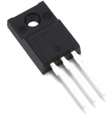
We feed in our battery line and a ground connection to the outer pins and take a 3V3 safe level to power the micro:bit.
Chassis - Motors
The next thing we need to do is to get the framework and motors for the vehicle. You could get the motors and make a base board to attach them to. For £10 or less, we can get a cheap pair of motors and an acrylic chassis for a basic 2WD kit with DC motors (two wheel drive). Pay a little more money and you generally get something nicer. Remember to check that the motor voltage is suitable for the power you are supplying. Some of the cheap kits will come with continuous rotation servos. These are no use for this circuit. The other thing to bear in mind is that you might need to solder wires to the motors, sometimes this is not done for you when buy a kit like this.
Bits & Bobs
Since this is a platform for experimentation and learning, I'm not so worried about tidiness, I just want to keep things working. For that reason, I'm going to use a breadboard stuck onto the chassis to hold the electronics. A mix of solid core wires will be used to jumper everything together.
Tada...
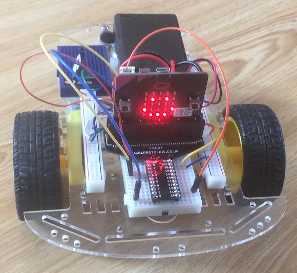
This is the finished prototype. I separated the power rails of the breadboard to fit them nicely on the board. The mini blue breadboard at the back has the voltage regulator and the motor driver board is squished onto the back of the breadboard. The blue breadboard is going to be used for tapping into the power for any parts that need a few more volts.
I've uesed the Proto-pic edge connector which, although expensive, has a lot of routing work done to make pin use easier and leaves the board upright for when I do want to use the LED matrix. Yes, it is shiny enough to reflect the LEDs of the matrix.
Although it's in a tiny space, I still have an easy way to connect parts to the GPIO Pins I still have free. They are in a neat spot for anything mounted at the front.
The circuit with the driver board is, in its simplest form, this,
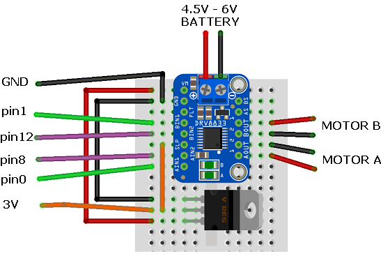
The connections on the left of the diagram are to an edge connector on a micro:bit. It is recommended to use a couple of capacitors with the voltage regulator - I found that things worked without doing that. Regulators like this have a dropout voltage, 4.5V is close to the minimum needed, 4 batteries might be a better standard option.
The voltage regulator and the motor driver board are going to get hot and warm their surrounding area. If you're going to be driving the vehicle for a while, try make sure you have things more spaced out than I have in the photograph above. And watch your fingers when picking up the robot or tweaking the circuit.
Programming
I set up the pin connections so that driving the motor would be the same as for the Bit:bot. This is the imperfect test version for remote control described on the page. I used this to test that the robot worked as it should.
Programming - Sending
Here is my code for the remote control. I'm using the accelerometer to go backwards and forwards by tilting the micro:bit and using the two buttons to make the robot turn left and right. Some arrows are used on the LED matrix to help with debugging.
from microbit import *
import radio

chnl = 10
radio.config(channel=chnl)
radio.on()


while True:
    y = accelerometer.get_y()
    a = button_a.is_pressed()
    b = button_b.is_pressed()
    if  a and y<-300:
        # forwards left
        display.show(Image.ARROW_NW)
        radio.send("NW")
    elif a and y>300:
        # backwards left
        display.show(Image.ARROW_SW)
        radio.send("SW")
    elif b and y<-300:
        # forwards right
        display.show(Image.ARROW_NE)
        radio.send("NE")
    elif b and y>300:
        # backwards right
        display.show(Image.ARROW_SE)
        radio.send("SE")
    elif y>300:
        #backwards
        display.show(Image.ARROW_S)
        radio.send("S")
    elif y<-300:
        # forwards
        display.show(Image.ARROW_N)
        radio.send("N")
    sleep(20)
Depending on the input, or combinations of input, a compass direction is sent to indicate the direction in which to drive the robot. A channel number is used. Radio isn't a direct one-to-one form of communication. If there are other people using the micro:bit radio in your vicinity, the receiving micro:bit is going to pick up and respond to those signals. There are channels numbered from 0 - 100. Our receiving micro:bit will only receive the messages that are sent on the same channel. The default value is 7. Change from that and no one else's radio can interfere with yours.
Programming - Receiving
Here is the script that receives the radio signal and drives the robot in the correct direction.
from microbit import *
import radio

chnl = 10
radio.config(channel=chnl)
radio.on()

def Drive(lft,rgt):
    pin8.write_digital(0)
    pin12.write_digital(0)
    if lft<0:
        pin8.write_digital(1)
        lft = 1023 + lft
    if rgt<0:
        rgt = 1023 + rgt
        pin12.write_digital(1)
    pin0.write_analog(lft)
    pin1.write_analog(rgt)

while True:
    s = radio.receive()
    if s is not None:
        if s=="N":
            Drive(800,800)
        elif s=="S":
            Drive(-800,-800)
        elif s=="NE":
            Drive(800,200)
        elif s=="NW":
            Drive(200,800)
        elif s=="SE":
            Drive(-800,-200)
        elif s== "SW":
            Drive(-200,-800)
    else:
        Drive(0,0)
    sleep(20)
Results
The above program gave me reasonable control of the vehicle using a second micro:bit. In this basic setup you have to expect a little bit of veering, sometimes a fair bit. This can be caused by natural variance in the performance of cheap motors, variations in the voltage received by each motor, insufficient voltage in the circuit, the mass and distribution of the load on the chassis, the type of caster or free wheel used.
Beyond the obvious fixes and checking the mountings of the motors, one way to compensate for predictable differences is in the code you use to drive them. Reduce the PWM value you send to the over-powered motor.
Another approach to deal with minor variations from straight is to use analog readings from the accelerometer for all movements. Get the settings right and the user naturally learns to compensate for the difference.
The final way to sort things out is to use wheel encoders to measure rotation of each motor. This is a whole other project though.
With controllable movement in all directions, the next thing to do is to reflect on what our platform makes possible for us,
We have access to 4.5V power, micro:bit power and the following unused GPIO pins,
| 2 | Touch | Pad 2 |
| 13 | Digital | SPI MOSI |
| 14 | Digital | SPI MISO |
| 15 | Digital | SPI SCK |
| 16 | Digital | GPIO |
| 19 | Digital | I2C SCL |
| 20 | Digital | I2C SDA |
We can use pin 2 as a touch input - which we could set up as a contact switch for detecting bumps. It's also an analog pin with PWM output. We can either use pins 13 - 16 with SPI breakouts or have them as digital GPIO. Pins 19 and 20 can only be used for i2c connections but that covers loads of sensors that we might want to use.
The buttons are not much use to use when they are being driven around on a robot car. They can be used for digital input. They're quite handy with digital line sensors where you can program your code for reading the sensors like you do for reading button presses. You can turn off the LED matrix and use the GPIO pins that are freed up too,
| 3 | Analog | Column 1 |
| 4 | Analog | Column 2 |
| 5 | Digital | Button A |
| 6 | Digital | Row 2 |
| 7 | Digital | Row 1 |
| 9 | Digital | Row 3 |
| 10 | Analog | Column 3 |
| 11 | Digital | Button B |
Three of those are analog pins. If you're not using the display much on the moving vehicle, you can repurpose a shedload of pins to use for your experiments on your robot friend.
Next Steps
The world is your oyster. You have lots of GPIO and you just need to connect up some components to them and make your robot friend your own. Or you can just use this a platform for testing out ideas that you want to put into a more carefully made version. It's worth working with the movement and remote control for some time to get things working as you want for your setup. Some things you might want to look into after that,
- Using encoders to control movement more precisely.
- Line sensors to do line following and maze solving.
- A simple buzzer for a vehicle horn.
- Some lights. These could be simple digital indicators, GPIO or shift register controlled LEDs are nice, so are Neopixels.
- Add servos, running them off the battery box supply rather than the micro:bit. These could move about lights for you.
- A speaker and some amplification to get the speech library kicking out some friendly phrases for you.
- You can connect a range of i2c devices if you can make them work on the micro:bit. An RTC allows your robot to perform according to the clock.
- The SPI pins can be used for sensors, data storage and displays that connect with that protocol.
- You could make a contact switch to act as a bumper for a collision.