BBC Microbit
![]()


BBC micro:bit
Dot/Bar Graph LED Driver
Introduction
The LM3914 integrated circuit is used to drive up to 10 LEDs at constant current using an analog source to determine which or how many LEDs to light. You can use it with separate LEDs or a group of them in a bar graph package. The IC works by comparing the analog signal it receives with a set of reference values taken from other inputs.
Although this page is positioned in the MicroPython section, you don't need to write a program to work with this chip. Instead, you can use this page as a hook-up guide for using the integrated circuit where your power supply is giving you 3V3.
Circuit
This is the pinout diagram of the integrated circuit that you can find on the datasheet,
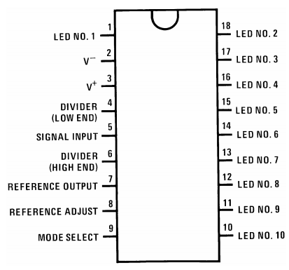
Pin 1 and the pins from 10 - 18 need to be connected to the cathodes of your LEDs. They are meant to sink the current from the LEDs, not supply the power to drive them.
V- and V+ are the power supply connections. You connect your GND to V- and your 3V3 supply to V+.
Pin 5 is connected to the analog signal that will determine which LED(s) to light.
Pin 7, is connectd to GND via a resistor. The value of the resistor determines the current through the LEDs.
Pins 4 and 6 are used to define the range of voltages that will produce an effect on the LEDs. The high voltage must be at least 1.5V lower than the power supply.
The mode select pin is driven high to put the chip into bar graph mode. This means that,as the voltage increases, additional LEDs are lit up. If the pin is left floating (unconnected), the chip is in dot mode. Only one LED at a time is lit.
The tricky part of this circuit is that, assuming you are using resistors to make voltage dividers to supply the reference voltages, the choice of resistor makes an enormous difference to the circuit. With 3V3, the maximum value we can get for the high reference is 1.8V. Resistors and the wiring of the circuit itself means that you cannot be 100% confident about knowing the exact resistance that will be fed to the pin. A little slack is needed. I've aimed for about 1.5V which is more than enough of a safety net.
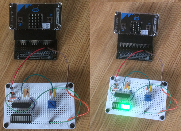
This is my finished, working circuit.
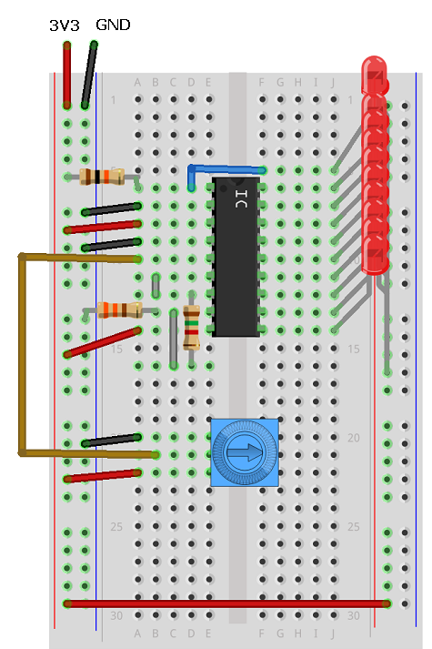
There are 3 resistors used in my circuit, 4 if you count the variable resistor (the trimmer potentiometer) that is being used as the analog signal source.
Resistor LED - 10K
This resistor is connected from 3V3 to the first LED. IT's the one at the top of the diagram. If you miss out this resistor, you might find that the first LED is on at times you expect it not to be.
Resistor 2 - 330 Ohm
The 330 Ohm resistor connects pin 8 to GND.
Resistor 1 - 1K5 or 1K8
This resistor is the one that, in this circuit, makes the most difference to the value we are supplying to the chip for its high reference.
Choosing the correct values for resistor 1 and 2 in this circuit is the key to making it work.
I used a spreadsheet to work out the best pair of resistors for my circuit. I was aiming for a VREF (voltage reference) of around 1.5V and to set the LED current to somewhere close to 10ma.
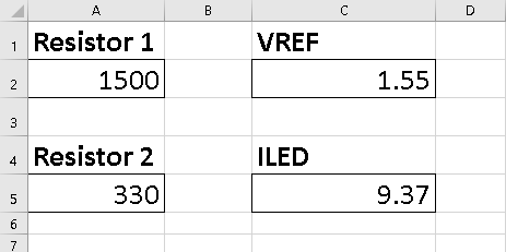
I actually used a 1K8 resistor in my circuit but couldn't show that in the circuit diagram. VREF is the value for our HIGH reference, ILED is the current going through the LEDs.
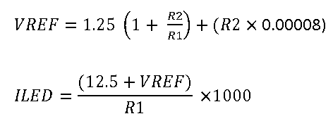
The following formulas were used,
You can see the circuit I made in the photograph below. The micro:bit is just providing the power supply. On the left, the potentiometer is turned fully towards the pin connected to GND. The second shot is with the potentiometer turned a bit. A full turn of the potentiometer takes the voltage from 0V to a value higher than our VREF. Once the VREF is reached, all of the LEDs are on. This makes for a fairly small range of voltages but you can quite easily use this potentiometer to select the LEDs one by one. In the photograph, the chip is in bar mode, so all of the LEDs up to the reading are lit.
If you are trying this circuit with a different supply voltage, you are likely to need to make quite a big change to the resistors you use. For 5V, you will want R1 to be about 2.2K and R2 to be about 3.3K.
Controlling With The micro:bit
Your first thought might be to think that you can PWM the signal pin and control the lights that way. Well, although PWM gives an approximation of an analog signal, that doesn't always mean that an analog component will recognise the signal as being true analog and respond that way. With this, PWM is the equivalent of blinking the LEDS on and off a lot. So we need to make a better analog signal if we want the microprocessor to control the LEDs.
This is when you need a DAC or digital to analog converter. When it comes to controlling LEDs, using a DAC seems like rather more technology than is needed and there are chips dedicated to doing that job for you in a much easier way. That didn't stop me wanting to do it. It is quite a nice way to make a circuit that has digital to analog conversion followed by analog to digital conversion, all in a chain.
The DAC I used was the Adafruit MCP47225 breakout. It costs around £5-6.
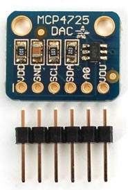
It works over the i2c interface and has 12 bit precision. This means that 0 - 4095 is the range of values we use to represent 0 to 3V3. This is more than enough for our needs here.
To make the circuit for this, first remove the trimmer potentiometer from the bread board and pop in the DAC. For this one, I need to make the following connections,
- Connect GND on the breakout to GND on the microbit.
- Connect VDD to 3V.
- Connect SDA to pin 20.
- Connect SCL to pin 19.
- Connect VOUT to pin 5 on the LM3914 (where you had the wiper from the potentiometer).
Programming
Thankfully, the i2c interactions you need for this component are minimal and pretty simple. We have to send a byte that tells the chip we are setting a voltage level. The next two bytes that you send represent the 12bit binary number used to select the output voltage. We have to send the leftmost 8 bits as the second byte. The last 4 bits are sent as the first 4 bits of the last byte. If we send two bytes, we have 16 place values. Our number has to be left-aligned on the place value table, shifted 4 places to the left.
The next thing to consider was the voltages that would be needed to trigger a level change on the LM3914. I went back to the spreadsheet I was making and divided the voltage spread into 10 spots. I then mapped those onto the 0 - 4095 range that we have,
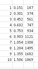
This was close to working but failed in a couple of spots. With a little adjustment, I got 10 values that, along with 0 could be stored in a list in the program and used to choose the level on the LM3914.
from microbit import *

WRITEDAC = 0x40
ADDR = 0x62

def SetVoltage(v):
    a = v // 16             # bits 11 - 4
    b = ((v % 16) << 4)     # bits 3 - 0
    i2c.write(ADDR, bytes([WRITEDAC,a,b]), repeat=False)

def SetLevel(a):
    triggers = [0,186,373,560,747,934,1121,1250,1450,1620,1868]
    SetVoltage(triggers[a])

while True:
    for i in range(11):
        SetLevel(i)
        sleep(1000)
These numbers proved reliable for me. Bad gif,
Challenges
The circuit used on this page leaves quite a small range of voltages to trigger the LED changes. The limiting factor for us here is that we're taking power from the micro:bit. You could power the LM3914 and bar graph part of a circuit separately from the micro:bit and still use it as an indicator for voltages that you might normally read on a micro:bit, from a 3V sensor, for example. I have breadboard power supply that gives 3V3 on one side and 5V on the other. Connect the GNDs together and power only the LM3914 with the 5V. You could still connect the sensor output to both the micro:bit pin and the signal in on the LM3914. You must take care when working with mixed voltages. Keep your head clear with this one. Use the formula to get the values for the resistors you'll need to give you a 3V3 VREF, with sensible current for your LEDs.
If you really went to the trouble of doing the DAC part of this as well, you might want to experiment a little more. You can switch the voltages pretty quickly. Some fancy effects can be achieved. Tie this up with a buzzer for a tune or use it as a way of counting to 10 as a score in a game.