BBC Microbit
![]()


BBC micro:bit
SN3218 Binary Clock
Introduction
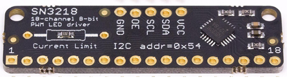
This project is a basic binary clock prototype using 17 LEDs, driven by an SN3218 LED driver integrated circuit. This is the same driver that is used for the PiGlow. You connect to it via i2c and can write PWM values for up to 18 LEDs. The board for this is made by the UK electronics company, Pimoroni. They don't seem to stock it any more but you can still find a few of the boards online in other shops. The board looks like this,
The Circuit
My prototype is shown in the photo. The time showing is 10:58 and 53 seconds. The first 5 LEDs from the left are the hours, the next 6 are the minutes and the final 6 are the seconds. It's not easy to make out the LEDs that are off in the photo.
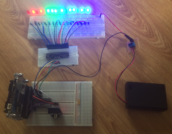
Although the photo doesn't show it well, I used 5 red LEDs for the hours, 6 green ones for the minutes and 6 blue ones for the seconds. On the large breadboard the LED anodes (longer pins) are all connected to the positive power rail. The positive wire from a 3xAA battery pack provides power for the LEDs. The ground wire is connected to GND on the micro:bit.
The shorter pins of the LEDs are connected to pins 1 to 17 on the SN3218 breakout.
On the other side of the breakout, the VCC and GND pins are connected to the 3V and GND pins on the micro:bit. SDA goes to pin20, SCL to pin19.
At the very bottom of the photograph of my protoype is the RTC. This is the DS3231 breakout that plays nicely at 3V. It has the same pin names that you get on the SN3218 breakout and they are connected up the same way.
The two i2c components can be connected to the same pins because an i2c address is used when communicating on these pins.
Sticking in this many pins takes a while, but it isn't complex. The micro:bit in this example is powered separately from the LEDs. A more sophisticated solution could separate and regulate the power supply for the micro:bit.
Programming
This is a quick program carving up the examples on the RTC and PiGlow pages. I'd already set the time using the approach described there.
from microbit import *

class piglow:
    def __init__(self):
        self.ADDRESS = 0x54
        self.reset()
        self.enable()
        self.enable_leds(0x3FFFF)
        self.update()

    def enable(self):
        i2c.write(self.ADDRESS,bytes([0x00,0x01]),repeat=False)

    def reset(self):
        i2c.write(self.ADDRESS,bytes([0x17,0xFF]),repeat=False)

    def update(self):
        i2c.write(self.ADDRESS,bytes([0x16,0xFF]),repeat=False)

    def enable_leds(self, mask):
        data = bytes([0x13,mask&0x3F,(mask >> 6) & 0x3F, (mask >> 12) & 0X3F])
        i2c.write(self.ADDRESS,data,repeat=False)
        self.update()

    def output(self, buffer):
        i2c.write(self.ADDRESS,buffer,repeat=False)
        self.update()
# RTC functions
def bcd2dec(bcd):
    return (((bcd & 0xf0) >> 4) * 10 + (bcd & 0x0f))


def get_time():
    i2c.write(0x68, b'\x00', repeat=False)
    buf = i2c.read(0x68, 7, repeat=False)
    ss = bcd2dec(buf[0])
    mm = bcd2dec(buf[1])
    if buf[2] & 0x40:
        hh = bcd2dec(buf[2] & 0x1f)
        if buf[2] & 0x20:
            hh += 12
    else:
        hh = bcd2dec(buf[2])
    wday = buf[3]
    DD = bcd2dec(buf[4])
    MM = bcd2dec(buf[5] & 0x1f)
    YY = bcd2dec(buf[6])+2000
    return hh,mm,ss,YY,MM,DD,wday

p = piglow()
leddata = bytearray(19)
leddata[0] = 0x01
while True:
    hh,mm,ss,YY,MM,DD,wday = get_time()
    # bit shift values into a 17 bit binary number
    t = (hh<<12) + (mm<<6) + ss
    for i in range(18):
        leddata[i+1] = (t>>i & 1) *255
    p.output(leddata)
    sleep(1000)
The PiGlow class is modified to accept a bytearray as an argument for the output method and non-essential methods are removed. The bytearray has to have 1 as the first byte, the other 18 represent the PWM values (0-255) for the LEDs.
When the time is read, the values are bit-shifted into a single integer. The binary value of this integer represents which of the LEDs should be on or off and is processed with the for loop.
Ideas
Although there are a lot of connections, this one is plausible for a semi-permanent or permanent version and the time spent developing the additional features expected from a clock. Something like this could be built into a cardboard box/tupperware/ABS enclosure,
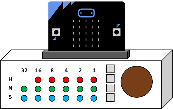
The edge connector is fixed to the top of the box. The top is an edge connector. The Sparkfun edge connector has all of the pins in a neat straight line. As well as the LEDs there are 4 buttons or so, in addition to the micro:bit buttons that can be used to set the time, and trigger other events. The round thing would be a speaker. Perhaps an indicator LED and a potentiometer for volume control could be added too.
There's enough kit here to make it interesting with components that can be found quite cheaply. An 18th LED could be placed in the empty space - redundant for displaying the time. It would form a 3x6 matrix that could be used for some lighting effects.
Adding a potentiometer would allow control of the LED brightness. A couple of pieces of foil on the outside of the box, connected to a touch pin, would add another input. If the innards of the beast can be fixed firmly, the whole thing could be shaken to deactivate an alarm.
In long term use, this would eat batteries. A decent power solution needs to be considered. With a breadboard hack in the box, I have a USB breadboard power supply that gives 5V and 3V3, both at the amounts of current needed. A longer term solution would be a voltage regulator on a line taken from the power supply to lower the voltage to micro:bit safe levels. If sticking with batteries, a 2xAA battery supply could be used, meaning less power for the LEDs, but no need for regulating.
The speaker allows for tunes and speech. Working up a speaking clock would be a nice direction for the project, along with some voice alarms for a polite awakening.
In summary, using the i2c pins for all the components in the example leaves too many GPIO pins free not to want to think about what else could be added.