BBC Microbit
![]()


BBC micro:bit
Kitronik RTC Board
Introduction
The Kitronik RTC Board is a micro:bit accessory from the UK supplier, Kitronik. The main purpose of the board is to provide an easy to connect real-time clock component along with some additional options for power and connecting other components.
The RTC used is the MCP7940-N which works in a similar way to the other RTCs that I have used. The board has a coin cell battery holder to backup the time data once set. There is a USB and power terminal input with voltage regulator that make it easy to power the board and micro:bit.
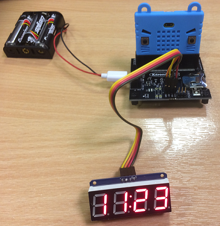
In the photograph, the RTC board is being used with a 7 segment display. The display is connected to an i2c breakout header on the front of the board. There is also a breakout for adding Neopixels. This breaks out the voltage in from the battery or USB connector and is a useful enough feature in itself to make the board worth using even without the RTC features. There is a full set of connections to all of the micro:bit pins on what Kitronik call a 'link' header (it can be chained to other products by the same company).
Programming
Although Kitronik's datasheet for the product says that there are MicroPython samples online, I wasn't able to find them. The datasheet and product page don't state the name of the RTC component either. Fortunately, everything I needed was buried in the code of the MakeCode library. With this and the datasheet for the MCP7940-N, it isn't too much to work out a basic library to get started with the board in Python. This was helped by having the MakeCode library in pure TypeScript with self-documenting code.
First Go
The first thing to do was just to set and read the time and date from the board. The following code was my first go, outputting the time and date to the REPL.
from microbit import *

a = 0x6F

def bcd2bin(value, mask):
    units = value  & 0x0F
    tens  = (value & mask) >> 4
    return tens * 10 + units

def bin2bcd(value):
    return (value or 0) + 6 * ((value or 0) // 10)

def setup_rtc():
    i2c.write(a, b'\x00')
    cs = i2c.read(a,1)[0]
    i2c.write(a, b'\x07\x43')
    i2c.write(a, b'\x03')
    cwd = i2c.read(a,1)[0]
    i2c.write(a,bytes([0x03,0x1F | cwd]))
    i2c.write(a,bytes([0x00,0x80 | cs]))

def get_time():
    i2c.write(a, b'\x00')
    buf = i2c.read(a,7)
    ms = [0x70,0x70,0x10,0x10,0x30,0x10,0xF0]
    tm = [bcd2bin(buf[i],ms[i]) for i in range(7)]
    tm[3] -= 8
    return tm

def time_str():
    t = get_time()[:3]
    t = t[::-1]
    s = ['{:02d}'.format(i) for i in t]
    return ":".join(s)

def date_str():
    t = get_time()[4:]
    s = ['{:02d}'.format(i) for i in t]
    return "/".join(s)

def set_time(t):
    i2c.write(a, b'\x00')
    i2c.write(a, b'\x00\x00')
    t[3] = 0x1f | t[3]
    for i in range(1,7):
        i2c.write(a,bytes([i,bin2bcd(t[i])]))
    i2c.write(a,bytes([0,0x80 | bin2bcd(t[0])]))

setup_rtc()

# uncomment to set the time
# the list is in register order
# seconds, minutes, hours, weekday, day, month, year

#set_time([0,5,12,7,25,11,18])

while True:
    t = get_time()
    print(time_str(),date_str())
    sleep(1000)
Using A Serial 16x2 LCD
With the RTC working, I thought it would be nice to see the time displayed on a character LCD. I used the Sparkfun serial LCD for this and just added the minimal code I needed to get that working.
from microbit import *

# blank string to clear LCD
clear = " "*32

# rtc address
a = 0x6F

# choose cursor position - row 0,1 col, 0-15
def move_cursor(row,col):
    cmd = [254,128]
    if row==1:
        cmd[1]+=64
    cmd[1]+=col
    uart.write(bytes(cmd))
    sleep(10)

def bcd2bin(value, mask):
    units = value  & 0x0F
    tens  = (value & mask) >> 4
    return tens * 10 + units

def bin2bcd(value):
    return (value or 0) + 6 * ((value or 0) // 10)

def setup_rtc():
    i2c.write(a, b'\x00')
    cs = i2c.read(a,1)[0]
    i2c.write(a, b'\x07\x43')
    i2c.write(a, b'\x03')
    cwd = i2c.read(a,1)[0]
    i2c.write(a,bytes([0x03,0x1F | cwd]))
    i2c.write(a,bytes([0x00,0x80 | cs]))

def get_time():
    i2c.write(a, b'\x00')
    buf = i2c.read(a,7)
    ms = [0x70,0x70,0x10,0x10,0x30,0x10,0xF0]
    tm = [bcd2bin(buf[i],ms[i]) for i in range(7)]
    tm[3] -= 8
    return tm

def time_str():
    t = get_time()[:3]
    t = t[::-1]
    s = ['{:02d}'.format(i) for i in t]
    return ":".join(s)

def date_str():
    t = get_time()[4:]
    s = ['{:02d}'.format(i) for i in t]
    return "/".join(s)

def set_time(t):
    i2c.write(a, b'\x00')
    i2c.write(a, b'\x00\x00')
    t[3] = 0x1f | t[3]
    for i in range(1,7):
        i2c.write(a,bytes([i,bin2bcd(t[i])]))
    i2c.write(a,bytes([0,0x80 | bin2bcd(t[0])]))


# get the RTC ready
setup_rtc()
# wait half a second for the splash screen
sleep(500)
# initialise uart
uart.init(baudrate=9600, bits=8, parity=None, stop=1, tx=pin12)

# clear display
move_cursor(0,0)
uart.write(clear)
move_cursor(0,0)

while True:
    move_cursor(0,0)
    uart.write(time_str())
    move_cursor(1,0)
    uart.write(date_str())
    sleep(1000)
Using A 7 Segement Display
Although the serial LCD works, it is a little dim when displaying the time. I then connected a 4 digit 7 segement display to the board. I used one of the Adafruit displays with an i2c backpack. The photograph at the top of this page shows the display connected to the i2c breakout header.
from microbit import *

class backpack:
    ADDRESS             = 0x70
    BLINK_CMD           = 0x80
    CMD_BRIGHTNESS      = 0xE0
    # Digits 0 - F
    NUMS = [0x3F, 0x06, 0x5B, 0x4F, 0x66, 0x6D, 0x7D,
        0x07, 0x7F, 0x6F, 0x77, 0x7C, 0x39, 0x5E, 0x79, 0x71]

    def __init__(self):
        self.buffer = bytearray([0]*16)
        i2c.write(self.ADDRESS,b'\x21')
        # 0 to 3
        self.blink_rate(0)
        # 0 to 15
        self.set_brightness(15)
        self.update_display()

    def set_brightness(self,b):
        i2c.write(self.ADDRESS,bytes([self.CMD_BRIGHTNESS | b]))

    def blink_rate(self, b):
        i2c.write(self.ADDRESS,bytes([self.BLINK_CMD | 1 | (b << 1)]))

    def write_digit(self, position, digit, dot=False):
        # skip the colon
        offset = 0 if position < 2 else 1
        pos = offset + position
        self.buffer[pos*2] = self.NUMS[digit] & 0xFF
        if dot:
            self.buffer[pos*2] |= 0x80

    def update_display(self):
        data = bytearray([0]) + self.buffer
        i2c.write(self.ADDRESS,data)

    def print(self,value):
        if value<0 or value>9999:
            return
        sdig =  '{:04d}'.format(value)
        dts = [int(x) for x in sdig]
        for i,d in enumerate(dts):
            self.write_digit(i,d)

    def set_decimal(self, position, dot=True):
        # skip the colon
        offset = 0 if position < 2 else 1
        pos = offset + position
        if dot:
            self.buffer[pos*2] |= 0x80
        else:
            self.buffer[pos*2] &= 0x7F

    def clear(self):
        self.buffer = bytearray([0]*16)
        self.update_display()

    def set_colon(self, colon=True):
        if colon:
            self.buffer[4] |= 0x02
        else:
            self.buffer[4] &= 0xFD

# rtc address
a = 0x6F

def bcd2bin(value, mask):
    units = value  & 0x0F
    tens  = (value & mask) >> 4
    return tens * 10 + units

def bin2bcd(value):
    return (value or 0) + 6 * ((value or 0) // 10)

def setup_rtc():
    i2c.write(a, b'\x00')
    cs = i2c.read(a,1)[0]
    i2c.write(a, b'\x07\x43')
    i2c.write(a, b'\x03')
    cwd = i2c.read(a,1)[0]
    i2c.write(a,bytes([0x03,0x1F | cwd]))
    i2c.write(a,bytes([0x00,0x80 | cs]))

def get_time():
    i2c.write(a, b'\x00')
    buf = i2c.read(a,7)
    ms = [0x70,0x70,0x10,0x10,0x30,0x10,0xF0]
    tm = [bcd2bin(buf[i],ms[i]) for i in range(7)]
    tm[3] -= 8
    return tm

def time_str():
    t = get_time()[:3]
    t = t[::-1]
    t = t[:2]
    s = ['{:02d}'.format(i) for i in t]
    return "".join(s)

def set_time(t):
    i2c.write(a, b'\x00')
    i2c.write(a, b'\x00\x00')
    t[3] = 0x1f | t[3]
    for i in range(1,7):
        i2c.write(a,bytes([i,bin2bcd(t[i])]))
    i2c.write(a,bytes([0,0x80 | bin2bcd(t[0])]))


# get the RTC ready
setup_rtc()
# uncomment the following and change to set time and date
#set_time([0,20,11,5,30,11,18])
f = backpack()

while True:
    ts = int(time_str())
    f.print(ts)
    f.set_colon()
    f.update_display()
    sleep(1000)
Summary
The RTCs that you can connect to microcontrollers have vary in their accuracy. I find that this one loses a little time between uses, enough to disrupt something that requires ultra-precise timekeeping but not enough to stop it being a perfectly usable clock component.
The most useful aspect of the product is the connectivity and power. You can get straight into programming without having to faff about with electrical connections. The edge connector and power in options mean that you could use this as the main board for any project, including robot vehicles and not have to worry about voltage regulation. With the Vin broken out for the Neopixel header, you would be able to feed your battery connection to other devices.
The code written here to control the RTC is not the most efficient. A more cutdown version might be needed in some projects to avoid memory being wasted. It might also be worth writing subroutines to allow the different values to be set or retrieved individually.