BBC Microbit
![]()


BBC micro:bit
4 LED Circuit
Introduction
For this project, you will build a circuit with 4 LEDs. The following picture shows what your finished circuit will look like,
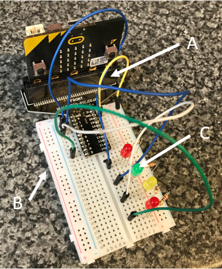
A
This is an edge connector. It makes it possible to connect components to the micro:bit.
B
This is called a breadboard. It allows us to plug in and connect components using jumper wires.
C
Each LED has two legs. The longer leg is positive. The shorter leg is negative.
The long leg is connected to a digital pin on the micro:bit. The pins used for this circuit are,
- Pin0
- Pin1
- Pin2
- Pin8
The short leg is connected to GND using a resistor, 200-330 OHMS.
The connections on a solderless breadboard work as follows,
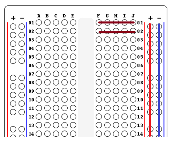
- The 5 holes that form a row on the breadboard are all connected together.
- The power rails (+/-) are connected together vertically.
- Connecting components to a breadboard is about making electrical connections.
- It is not about the exact position you choose on the breadboard.
- The colour of a jumper wire does not make any difference in an electrical circuit.
Task 1
Your first program is just to test that the circuit is connected correctly.
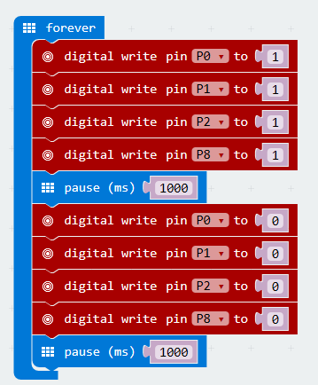
In order to turn on an LED, we use a digital write block and write a HIGH signal by choosing to write a 1.
To turn the LEDs off, we digitally write a 0 to the pin that the LED is connected to.
Speak to your teacher if you don't see all of the LEDs flashing on and off. Or, have a go at correcting the circuit yourself, using the photograph and explanations to help you.
Task 2
Write a program to turn the LEDs on one at a time. There should be a 1 second pause between each LED turning on.
Add your blocks to ON START so that the lights just turn on one by one.
Task 3
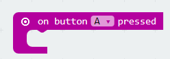
Write a program using the following blocks,
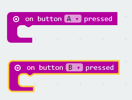
Make it so that the LEDs come on when you press the A button and go off when you press the B button.
Also use an ON START block in your program and turn all of the LEDs off when the program first starts.
Task 4
Change the program that you wrote for Task 3 so that,
- Pressing the A button turns 2 of the LEDs on and turns the other 2 off.
- Pressing the B button does the same but with 2 different LEDs.
Task 5
Start off a program using the following block,
Create a variable to use in this program. When the button is pressed,
- Turn all of the LEDs off.
- Set the variable to a random number from 0 to 3
- Display this number on the LED matrix of the micro:bit
- Use an IF block (with 2 ELSE Ifs, 1 ELSE) to turn one of the LEDs back on at random.
Task 6
Using analog writeUsing analog write blocks instead of digital write, allows you to set the brightness of the LED. You can write any value from 0 to 1023. 1023 is full brightness. Some of the lower values here will not be bright enough to be seen.
The following program uses a FOR loop to fade in the first LED.
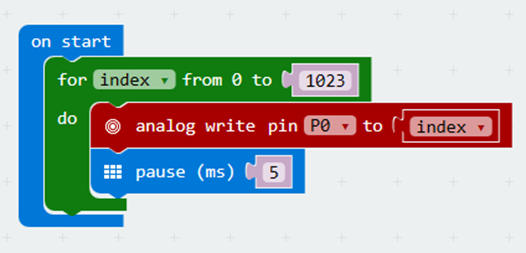
Adapt this program by adding the 3 analog write blocks required to fade in the other 3 LEDs.
Task 7
If you take the code from Task 6 and you write 1023 - index, you can make the LEDs fade out. Try that.
Task 8
Experiment with a program that allows you control the brightness of the LEDs using the two micro:bit buttons. I recommend using a variable and setting it to 0 when the program starts (ON START). When the A button is pressed, add 100 to the variable. When the B button is pressed, subtract 100 from the variable (CHANGE ... BY).
Add a FOREVER block. If the brightness variable is greater than 1000, set it to 1000. If it is less than 0, set it to 0. Then use analog write blocks to write that variable to the LED pins.