BBC Microbit
![]()


BBC micro:bit
USB Keyboard
Introduction
When you want a portable method for entering text, you either consume GPIO buttons on input devices or rely on scrolling through characters to select the one you want. For this project I used a USB host board from the UK electronics company Hobbytronics. I had already used an older one of their USB host boards to connect a PS3 controller. This time I used their USB Host Mini V2.0 with pre-installed USB keyboard software. It costs £14 and can be reprogrammed according to the device you want to use.
The keyboard I used is a wireless mini keyboard that has a 2.4Ghz USB receiver. It has no branding or model name on it The USB host board won't work with wired keyboards that have their own built-in USB hub - the item listing states this. I felt that the wireless keyboard I had was worth a go and it worked well. At this point, I am not sure whether I was fortunate or whether many/most of the these dongles will run nicely at 3V3. I have since used another small wireless keyboard, one of those cheap sub £10 ones that is shaped like a remote control. Worked perfectly too. Obviously, you lose the mouse functions on these devices.
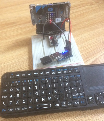
The Circuit
I made 3 connections to the USB host board. I connected the micro:bit power pins to 5V and 0V on the board. I connected pin0 of the micro:bit to the TX pin on the USB host board. Those are the 3 cables that you see in the photograph above.
Powering the USB host board with a 5V supply and using logic level shifting is more likely to work with a wired keyboard or one that is a bit more picky about the signals than mine.
Programming
The board works with UART or i2c. The examples here are all using UART and are quite basic. There are a lot of keys on a keyboard. There is a lot more information on this page.
Seeing It Work
If you use a UART connection, you lose the debug output you can see in the REPL window when using Mu. This first program was all about looking for the kinds of characters I wanted to input and seeing that they are correctly detected. Pressing letter keys and getting no output with this program means that something is wrong (circuit not correct or power needs not met).
from microbit import *

uart.init(baudrate=9600, bits=8, parity=None, stop=1, rx=pin0)
esc = 0

while True:
    if uart.any():
        a = uart.read(1)[0]
        if a==27:
            esc = 1
        else:
            if esc==1:
                # read excape character
                esc=0
            else:
                if a<27:
                    # read enter key
                    if a==13:
                        display.show(Image.HAPPY)
                        sleep(250)
                        display.clear()
                else:
                    # read normal character
                    c = chr(a)
                    if c.isalpha() or c.isdigit():
                        display.show(chr(a))
                        sleep(250)
                        display.clear()
    sleep(50)
The program reads a byte at a time from the device. If it reads 27, then one of the escape characters mentioned on the product page has been hit. Numbers below 27 represent special keys like the enter key. If the character is an alphabetic character or a digit, it is displayed on the LED matrix for a quarter of a second.
Entering A String
The next example has a function that reads alphanumeric characters until the user presses the enter key. This then becomes a message that scrolls on the LED matrix.
from microbit import *

uart.init(baudrate=9600, bits=8, parity=None, stop=1, rx=pin0)

def kbrd_str():
    a = 0
    output = ""
    esc = 0
    while a!=13:
        if uart.any():
            a = uart.read(1)[0]
            if a==27:
                esc = 1
            else:
                if esc==1:
                    esc=0
                else:
                    if a==13:
                        display.show(Image.HAPPY)
                        sleep(250)
                        display.clear()
                    elif a>31:
                        # read normal character
                        c = chr(a)
                        if c.isalpha() or c.isdigit():
                            display.show(c)
                            output += c
                            sleep(250)
                            display.clear()
    sleep(20)
    return output

display.scroll("Enter message.")
msg = kbrd_str()
while True:
    display.scroll(msg)
    sleep(50)
Arrow Keys
This last example uses the arrow keys on the keyboard to move a dot around on the LED matrix.
from microbit import *

uart.init(baudrate=9600, bits=8, parity=None, stop=1, rx=pin0)

# pixel coordinates
x = 2
y = 2

# set the pixel at the start
display.set_pixel(x,y,9)

# list of arrow key bytes
arrows = [0x48,0x50,0x4B, 0x4D]

while True:
    if uart.any():
        a = uart.read(1)[0]
        if a in arrows:
            display.set_pixel(x,y,0)
            if a==0x48:
                y -= 1
            elif a==0x50:
                y += 1
            elif a==0x4B:
                x -= 1
            elif a==0x4D:
                x += 1
            # keep on grid
            x = max(0, min(x, 4))
            y = max(0, min(y, 4))
            # update
            display.set_pixel(x,y,9)
Using I2C
When I found that I wanted to use the display in another project using UART, I looked again at the i2c interface. It turned out to be even easier to use than the UART. Here is a basic approach that you can use with the REPL.
from microbit import *

# keyboard functions
def get_num_chars():
    i2c.write(0x29,b'\x01')
    data = i2c.read(0x29,1)[0]
    return data

def read_buffer():
    n = get_num_chars()
    i2c.write(0x29,b'\x00')
    data = i2c.read(0x29,n)
    txt = [chr(i) for i in data]
    return txt

while True:
    if get_num_chars()>0:
        print(read_buffer())
    sleep(10)
Summary
It's quite easy to read from the keyboard using UART and the signals were extremely reliable for detecting keypresses. You need to bear in mind that the micro:bit is going to be receiving signals even when you aren't expecting it. As you are getting ready to read some input, it's worth clearing the serial buffer by doing uart.readall(). You might also notice that it is possible to have your display out of synch with the user's actions if, as with the first few programs, the delays are large.
The board is tiny and the USB receiver for the keyboard doesn't add a gread deal of bulk to it. It would fit pretty neatly in a project case using a wireless keyboard.
You're talking about 25 quid to get a full keyboard connected to the micro:bit with easy connections and that is easy to program with, particularly using i2c. That sounds like a lot, but I'm adding the cost of the keyboard that I use everyday anyway to remote control a PC and with a Raspberry Pi. The other thing is that you don't have to work hard to distinguish single button presses - very reliable. To get to something that presents itself to the micro:bit so simply, I'd struggle to get close to the cost. Using the small wireless remote control keyboards is quite handy for all sorts of remote control microcontroller stuff and the host board is going to get some reuse if you stick with microcontrollers for a time.
Some Ideas
A simple first step would be to adapt the code from the second example so that the user can press a micro:bit button to change the message that is scrolling.
If the LED matrix is the main output, improved timings and animation might help during input. Having something that represents a blinking cursor is a reasonably way to show the user that input is expected.
Sending radio messages is a must for this and it will be technically possible to send messages that are free of insults or rude words.
The keyboard would pair nicely with an LCD character display or multiple 7 segment display. Making the input this much easier draws attention to the limitations of the output. With the character display, you can allow the user to edit their text before submission. This brings into play the backspace, delete and arrow keys, maybe even home and end, who knows? The keyboard/character display option is pretty useful for any application that depends on gathering a range of inputs from the user. It's also useful when a project cannot be tested close to the computer where you program it (like a robot). Sometimes, your program depends on constants/thresholds that you want to adjust without having to go back upstairs to the room with your computer - the one with the carpet that your robot car hates.
Instead of taking the straightforward input from the keyboard and using it as letters, treat the keyboard as a bunch of buttons and do something cool for each one of them. A buzzer with different notes would be pretty cool. You can also map a key for each of the pixels on the LED matrix. That simplifies the input for a handful of games you might design.
A medium-sized project would be to use keyboard input and an SN3218 LED driver to make Noughts & Crosses. The LEDs could be arranged in pairs (different colours for each player) as a 3x3 grid.
Barcode readers and other devices that generate ASCII are going to work with this, providing their power and logic needs are met. A barcode reader is an interesting way to control a project. With optical devices like this, power is going to be an issue. The USB host board needs to have its own power supply if you are using a wired device.