BBC Microbit
![]()


BBC micro:bit
Qwiic MP3 Trigger
Introduction
The Sparkfun Qwiic MP3 Trigger is a breakout board that plays mp3 files. The 'trigger' part refers to the fact that you can use it with just some pushbuttons (and no microcontroller) and have it play mp3 files on button presses. When used with a microcontroller like the micro:bit, you communicate with it over i2c and can carry out most operations that you would expect from a basic mp3 player. It costs a little over £20.
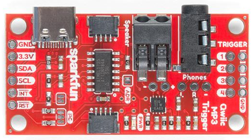
The photo shows the many connection points on the breakout board. On the far left are the pins for i2c connection. At the top left is a USB-C connector which can be used to power the board. Next to that is a Qwiic connector which, with the right cable, could remove the need for any other headers to be soldered. There is a connection for a speaker and, next to that, a headphone jack. Over on the right hand edge are the trigger pins. On the reverse of the board is a holder for an SD card. You put your tunes on that.
Circuit
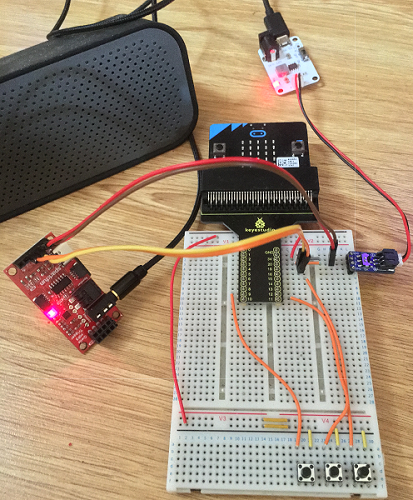
Here is my test circuit for the board.
Power
At the top right of the photo is a power board from Elecfreaks. It accepts a USB connection and spits out a clean 3V3 which can be fed directly to the micro:bit via a JST connector. Instead of plugging that into the micro:bit, I connected it to a JST breakout board so that I could tap into the same power source for the micro:bit and the mp3 trigger board. You don't want to power the mp3 board from the micro:bit. From the JST breakout, I connected to the 3V and GND pins of the micro:bit as well as the same on the mp3 trigger.
Audio Out
I started off with some headphones but, I wanted to test out the volume changing features and moved onto a powered speaker instead. The one I used here is USB charged and ran on battery power in this circuit.
Buttons
I used 5 buttons in my test program. The two micro:bit buttons were used for volume up and down. I added 3 more pushbuttons. Since it is now possible to activate the internal pull-up resistors on the digital pins, I decided not to use any external resistors on the buttons and use them with pull-ups as I prefer to do in circuits.
Programming
I placed 5 mp3 files on the SD card. Buttons A and B are used to adjust the volume. The pushbuttons are, from left to right, play/pause, next and previous.
I used Sparkfun's hook-up guide as a reference - here it is. I found that the multi-byte commands only worked properly if I sent the write byte separately from the command bytes, but otherwise, following the guide as is worked pretty well.
from microbit import *

# single byte commands
def w1(c):
    i2c.write(0x37,bytes([c]))

# 2 byte commands
def w2(c,v):
    i2c.write(0x37,b'\x6e')
    i2c.write(0x37,bytes([c,v]))

def stop():
    w1(0)

def next():
    w1(4)

def prev():
    w1(5)

def pause():
    w1(3)

def get_volume():
    i2c.write(0x37,b'\x6e')
    i2c.write(0x37,b'\x0e')
    return i2c.read(0x37,1)[0]

def vol_up():
    v = min(get_volume() + 1,31)
    w2(7,v)

def vol_down():
    v = max(get_volume() - 1,0)
    w2(7,v)

# set the internal pull-up resistors
# on the button pins
pin8.set_pull(pin8.PULL_UP)
pin12.set_pull(pin12.PULL_UP)
pin16.set_pull(pin16.PULL_UP)

# set volume to low
w2(7,6)
# play the first file
w2(1,1)

while True:
    if button_a.was_pressed():
        vol_down()
    elif button_b.was_pressed():
        vol_up()
    if pin8.read_digital()==0:
        w1(3)
        sleep(150)
    elif pin12.read_digital()==0:
        w1(4)
        sleep(150)
    elif pin16.read_digital()==0:
        w1(5)
        sleep(150)
    sleep(20)
Review
I was very pleased with this test project. Adding a display and refining the program a little would make for quite a usable mp3 player. The connectivity and power options on the mp3 trigger board make it pretty easy to work with. I didn't try any of the other commands out but probably will get around to doing so in a future project.