BBC Microbit
![]()


BBC micro:bit
Touch pHAT CAP1166
Introduction
The Touch pHAT is a breakout board intended for the Raspberry Pi. It has 6 capacitive touch sensors and 6 LEDs. The LEDs are white and mounted underneath the board. You see a yellowy green glow when you light them up. The board uses a CAP1166 integrated circuit to do the sensing and to to control the lights. This is done using the i2c protocol.
The Touch pHAT is made by the UK electronics company, Pimoroni. It works well with the micro:bit and gives you 6 extra touch inputs and some LED indicators that match up with the inputs.
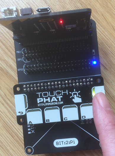
In this image, you see the micro:bit and Touch pHAT connected to a Bit:2:Pi. This board is made by the UK electronics company, 4tronix. There is a battery box underneath the board powering the micro:bit and the pHAT. The 3V3 and 5V connections are made for you. That made a portable controller with 6 buttons. The whole package can be operated two-thumb style if you can keep your hands way from the edges.
Circuit
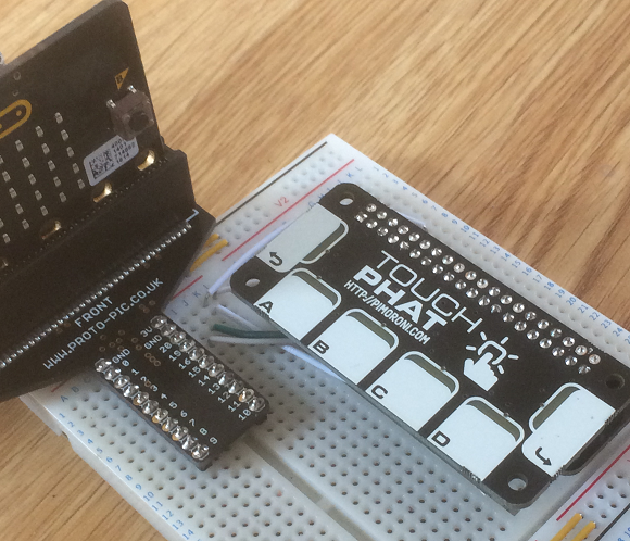
In the image above, the micro:bit is connected to the breadboard using an edge connector. The Touch pHAT is connected to a Raspberry Pi GPIO connector, which is connected to the breadboard. You could use a different brand of edge connector, a different means of connecting to the pHAT (directly with cables in the headers, using a 4tronix Bit:2:Pi) and a different type of breadboard. As long as you connect the correct pins together, you should be able to make this work.
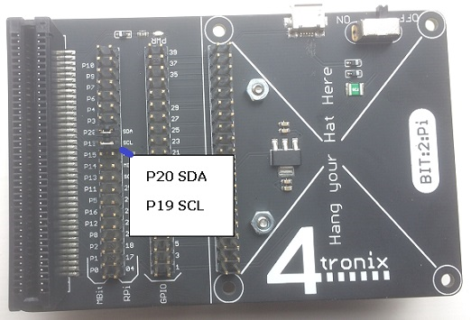
The image at the top of the page shows the Touch pHAT on a Bit:2:Pi. Apart from making sure that the Data (SDA) and Clock (SCL) connections are made with the jumpers, you only need to add some batteries for this to work. Then you have a handheld touch-enabled controller.
Pin Connections
| Connection | Raspberry Pi | micro:bit |
|---|---|---|
| Power LED | 5V | 3V |
| Power IC | 3V3 | 3V |
| Ground | GND | GND |
| Data | Pin 2 | Pin 20 |
| Clock | Pin 3 | Pin 19 |
Programming
Here is a basic class to test the connections to the board.
from microbit import *

class touchphat:

    def __init__(self):
        self.SENINPUTSTATUS = 0x03
        self.LEDLINK = 0x72
        self.LEDSTATUS = 0x74
        self.STANDBYCFG = 0x41
        self.ADDRESS = 0x2C
        self.LEDTRACK = False
        self.write_reg(self.LEDLINK,0x00)
        sleep(1)
        self.write_reg(self.STANDBYCFG,0x30)
        sleep(1)

    def write_reg(self,reg,value):
        i2c.write(self.ADDRESS, bytes([reg,value]), repeat=False)

    def read_pads(self):
        self.write_reg(0,0)
        i2c.write(self.ADDRESS, bytes([self.SENINPUTSTATUS]), repeat=False)
        data = i2c.read(self.ADDRESS,1,repeat=False)
        if self.LEDTRACK:
            pattern = sum(1<<(5-i) for i in range(6) if data[0]>>i&1)
            i2c.write(self.ADDRESS, bytes([self.LEDSTATUS]), repeat=False)
            led_state = i2c.read(self.ADDRESS,1,repeat=False)
            if pattern != led_state[0]:
                self.set_leds(pattern)
        return data[0]

    def read_pads_list(self):
        pattern = self.read_pads()
        bits = [pattern >> i & 1 for i in range(5,-1,-1)]
        return list(reversed(bits))

    def set_led_tracking(self, led_follow):
        self.LEDTRACK = led_follow

    def set_leds(self, led_byte):
        self.write_reg(self.LEDSTATUS,led_byte)


tphat = touchphat()
tphat.set_led_tracking(True)
while True:
    a = tphat.read_pads_list()
    display.clear()
    if a[0]==1: display.set_pixel(0,0,9)
    if a[1]==1: display.set_pixel(0,4,9)
    if a[2]==1: display.set_pixel(1,4,9)
    if a[3]==1: display.set_pixel(2,4,9)
    if a[4]==1: display.set_pixel(3,4,9)
    if a[5]==1: display.set_pixel(4,0,9)
On the board, the LEDs are connected to the output channels in reverse order. The integrated circuit does have a mode for making the LEDs light up automatically. It needs to be switched off here when the sensor is initialised. This example includes the logic for lighting up the LEDs each time the status of the inputs pads is read.
Notice that there are no delays in the main loop of this program. If we have the LEDs track the sensor readings, we need to have them happen a lot.
This example shows how to read which of the pads 0-5 has been touched. The default mode for the chip is multitouch, meaning more than one sensor can be touched at a time. It uses the read_pads_list method to get the reading as a convenient list, with the pads numbered 0-5, left to right on the board as you see them. The other method returns a byte, where the bits are set to 1 if the pad is touched. The rightmost bit, is the leftmost pad. This is a useful value to read in some situations, particularly if you want to see if the touch input has changed since last reading. For example,
last = 0
while True:
    current = tphat.read_pads()
    if last != current:
        # Input pattern has changed since last reading

    # end of loop
    last = current
Each unique combination of inputs results in a different bit pattern, making a different number. If you are using combinations of pad presses as inputs to a program, writing the combination as a single byte will help. In this example, the variable last is being used as a follower.
You can set the LEDs by writing a bit pattern to the correct register on the IC. A separate method for reading this register is not included in the example, but might prove useful. Remember that the bits need to be reversed to match the pad numbers we are reading.
Challenges
You should start by testing that you have the circuit correctly wired up. Then work out where you want to go with this board with some of the following ideas,
- Replace the button or other digital input in an existing project with input from the board.
- Match the inputs up to some frequencies and sound one of them on a buzzer, depending on the input. A simple way to deal with the default multitouch behaviour is to use an if..elif structure, which effectively assigns a priority to your buttons.
- Make pretty patterns with the LEDs, cycle them on and off, blink about a bit, you know.
- Rework the Simon game for this pHAT. You will need a buzzer. Other than that, see if you can use the lights on the board and the touch pads to make the game. You can choose whether or not to have a 6 input version.
- There is a lot more functionality to this integrated circuit. Search for the CAP1166 datasheet and scroll about 30 or so pages in to find a table of registers. You should be able to work out which registers you need to read and write in order to get more out of the IC. You can, for example, vary the brightness of the LEDs, change the sensitivity of the sensors individually, prevent multiple touches being detected and much more. Have a play with whatever interests you.