BBC Microbit
![]()


BBC micro:bit
PXT Radio
Introduction
PXT gives you blocks that allow you to access the radio. This makes some of the other libraries, like bluetooth, unavailable, but is worth it for the chance to communicate between micro:bits.
I used the radio functions of the block editor to make the remote control for a robot vehicle. See the pages in the Bit:Bot section for PXT.
Programming
Here is a simple program that you can put on two micro:bits and see working pretty well.
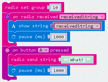
The group for the radio is a number from 0 to 255. Think of it as a channel. The micro:bit will only pick up messages sent on the same channel. Set this differently to other people if working in pairs in class.
radio.setGroup(10)
radio.onDataPacketReceived(({receivedString}) => {
    basic.showString(receivedString)
    basic.pause(1000)
})
input.onButtonPressed(Button.A, () => {
    radio.sendString("What?")
    basic.pause(1000)
})
It's more interesting to think about there being different programs on the two micro:bits. Next, we'll send movements from one micro:bit to another to control a dot on the screen.
We'll start with a two button system of movement. The B button will move down the grid, the B button to the right. We'll wrap back to the beginning after the last place. Here's just that part. I've adoided using the Game library because this approach gives you more control in the end.
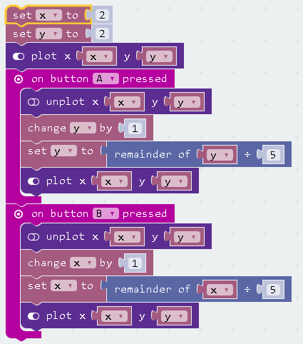
let x = 2
let y = 2
led.plot(x, y)
input.onButtonPressed(Button.A, () => {
    led.unplot(x, y)
    y += 1
    y = y % 5
    led.plot(x, y)
})
input.onButtonPressed(Button.B, () => {
    led.unplot(x, y)
    x += 1
    x = x % 5
    led.plot(x, y)
})
We don't have to do too much to this to make it send those movements to another micro:bit on a specific radio channel.
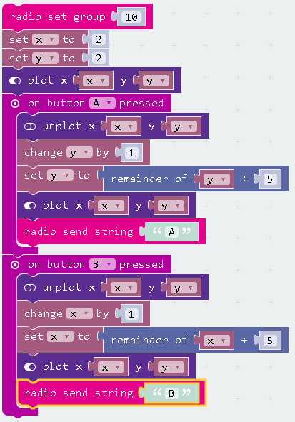
radio.setGroup(10)
let x = 2
let y = 2
led.plot(x, y)
input.onButtonPressed(Button.A, () => {
    led.unplot(x, y)
    y += 1
    y = y % 5
    led.plot(x, y)
    radio.sendString("A")
})
input.onButtonPressed(Button.B, () => {
    led.unplot(x, y)
    x += 1
    x = x % 5
    led.plot(x, y)
    radio.sendString("B")
})
Now we need to program our receiving device to move its pixel based on the radio signals. The receiving code is similar but has the logic encoded in an IF statement inside a single event. With two micro:bits on my desk, this had the dots on both devices in synch after a serious button mashing.
To write the IF statement, I put in the quotes that you see in the JavaScript in that editor and then switched back to the blocks.
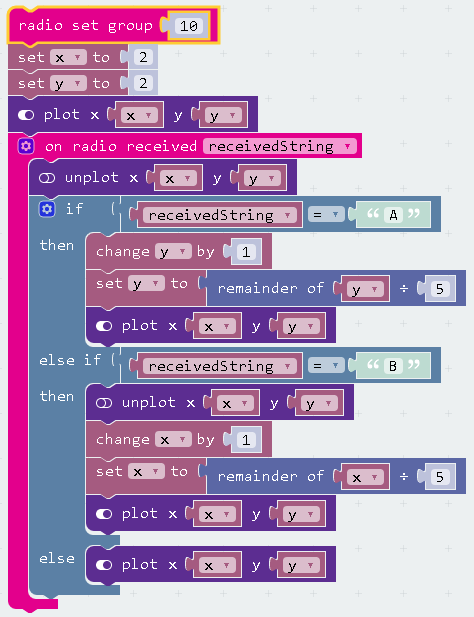
radio.setGroup(10)
let x = 2
let y = 2
led.plot(x, y)
radio.onDataPacketReceived(({receivedString}) => {
    led.unplot(x, y)
    if (receivedString == "A") {
        y += 1
        y = y % 5
        led.plot(x, y)
    } else if (receivedString == "B") {
        led.unplot(x, y)
        x += 1
        x = x % 5
        led.plot(x, y)
    } else {
        led.plot(x, y)
    }
})
Challenges
- The simplest version of this system is to send phrases based on inputs on one micro:bit. Using all manner of possible inputs (accelerometer gestures, pin touching), work out how many different understandable messages you can send from one micro:bit to another.
- Make a remote control human. Use inputs on one micro:bit to another micro:bit that is in the hands of the human that you wish to control. Use images of arrows and emoji style images to tell them how to move. You program the human part of this circuit by telling them that they have to do what the micro:bit tells them to or they are standing in the way of scientific progress. Design an interesting track or route for the human to follow and direct them perilously and hilariously close to the strictly non hurty hazards you have set up for them.
- The dot moving example is a way you could set up a simple battleships game. Focus on doing things in one direction first. Draw a fixed number of dots on the matrix of the receving micro:bit. Use the dot moving code and add an event for when both buttons are pressed. This is when the receving micro:bit checks for a hit at that location. If it finds one, it sends a message back to the player. This is quite a complex set of things to do so break it into small steps. Even if you don't end up with a fully playable game, some of your steps along the way will prove useful in other programs and for similar ideas.
- With 3 of you, you can make a micro:bit quiz scoreboard with or without remote control humans. One micro:bit is the scorer and simply sends out an A or B when a point is to be added to the team. Each team's micro:bit is programmed to respond to it's own letter. You could show a tick or arrow to move them forward or display their total number of points on the display. You could also attach lights to each of the team micro:bits to indicate progress towards a target total.
- Can you get one master micro:bit to reliably tell you which of a group of micro:bits in a group pressed a button first? You could get them to send a letter on a particular channel and check for this in your code. You could also think of the master as being in different states, waiting for a letter, receiving the first letter, ignoring letters. When the master presses the A button, set a variable to equal "Z" - a letter that no team would be allocated. Use the JavaScript editor to quickly add the quotation marks. When a message is received, check the value of this variable. If it equals Z, set it to the letter you have received and display that on the master. If you write the code for each team's buzzer to light up the LED when they receive their own letter, you can show the winning team if they buzzed in first.
- Connect buzzers up to two micro:bits. See if you can send a timing signal from one micro:bit to the other to play a simple harmony.
- Connect up buttons to one micro:bit and LEDs to another. Look in the pins sections for how to respond to changes in the state of a pin. Send these with the radio from the micro:bit with the inputs to the one with the outputs. Experiment with any other components you have using one micro:bit to receive the input and another to display something about it.
- If you work through all of the inputs you can detect on the micro:bit you can make multiple remote controls for a single micro:bit. If the device you have attached is a buzzer, you only need one micro:bit to have the buzzer attached if the buzzer is set to play notes as it receives radio messages from the remote controls. With a group of you, you can play a wider range of notes and, with some practice, a tune. This is even better if you do this with MIDI and have the micro:bits playing different instruments.
Big Screen Team Challenge 1
The example of using one micro:bit to control the position of the dot can be extended to use the displays of several micro:bits listening to the same radio channel. Start by setting down the micro:bits you on a table and arranging them into a grid like this,
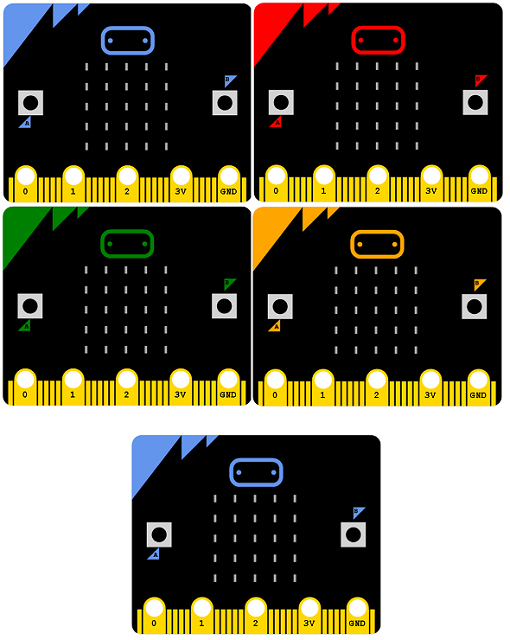
The 4 micro:bits in the grid form the extended screen. The one at the bottom is the controller.
The new composite matrix we have has a bigger coordinate space,
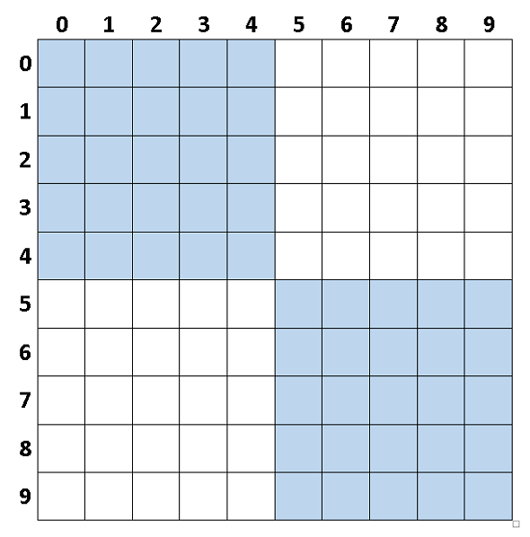
Program the master to start in the top left corner screen (x and y as 0). You need to change the 5 to a 10 if you are using a 4 microbit screen like this.
Each of the 4 micro:bits needs to keep track of the x and y values of the dot on this larger grid. The issue is that they no longer always have to unplot and replot the dot. Each dot will only need to do this with some of its LEDs depending on its position on the grid as a whole. If the current value of x and y stored in the top left micro:bit is a value on its part of the big grid, it has to unplot the current dot. When it has accounted for the movement, it has to draw the dot on the screen if x and y are still in the 0 to 4 range.
The micro:bit in the top right has to do something similar. It starts with values for x and y set to different numbers to the others and the master. Its value for x starts at -5. It can use the same logic to decide whether or not to unplot and replot the pixel, only unplot if x and y are in the 0 to 4 range, only plot if the change takes them into the 0 to 4 range.
Similar adjustments made to the starting values for x and y on the other micro:bits will be needed.
Once you have the moving dot working with the remote control, try working on programs for automating the movements. How about the dot moving around randomly or in a set pattern using a loop and some pauses to create an animation?
On the micro:bits, the different start values for x and y might be called an offset, an amount you subtract from the value of x to work out if it is on screen. The top left screen has no offset, or rather its offsetX and offsetY are both 0. The top right one in our 2x2 grid has an offsetX of 5 and a offsetY of 0. By having variables for these set at the start of your receiving program, you can work out an efficient way to recreate the system with different numbers of micro:bits.
By having variables for the grid size set at the start of the master control program would make it easier to reuse the project with different numbers of micro:bits and make it easier to adjust a saved program to a new setup.
If the dot drawing logic were in a forever loop on the receivers, the dot could be flashing when on the screen of an indivudal micro:bit.