BBC Microbit
![]()


BBC micro:bit
Sensing Light (PXT)
Introduction
On the end of each of the fins is a tiny light sensor. With two of the three analog pins already in use for driving the motors, these two analog sensors are both connected to pin 2. There is a select pin, pin 16. You write a digital 0 to this pin to read the left light sensor, a 1 to read the right sensor.
Having two light sensors means that you can compare the two readings and use that difference in light levels to decide how to move the robot. You can also use average of the two readings to get a sense of the light level in a room.
The readings you get from light sensors vary a lot. You get a reading of 0 when it is completely dark to 1023 when there is bright light shining on the sensor. The background reading, when you are not shining a light on the sensor or covering it up, depends entirely on the lighting of the place where you are working.
Programming
This first program demonstrates how you read the values from each of the sensors. The blocks from the serial library will output the readings for us on the serial port. For this to work on a Windows machine, you need to have installed the mbed serial driver, which you can get from from here.
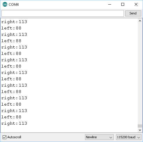
Now you need something that can read those signals. Here I've used the serial monitor that comes with the Arduino IDE. You need to select the serial port that your micro:bit is attached to the computer - usually the highest number. Set the baud rate to 115200 and you will see the figures scrolling across the screen,
Here are the blocks,
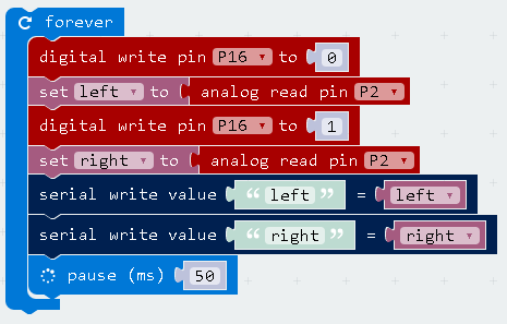
The JavaScript for this is,
let right = 0
let left = 0
basic.forever(() => {
    pins.digitalWritePin(DigitalPin.P16, 0)
    left = pins.analogReadPin(AnalogPin.P2)
    pins.digitalWritePin(DigitalPin.P16, 1)
    right = pins.analogReadPin(AnalogPin.P2)
    serial.writeValue("left", left)
    serial.writeValue("right", right)
    basic.pause(50)
})
This first program is used to get a sense of the light readings you get in the room where you are working. You also need to test the impact of introducing a light source around the sensors and how the readings change.
This second program is the simplest version of a light following program. It demonstrates the principle but needs a lot of optimisation. The program compares the two readings on the sensors and makes the robot head in the direction of the brighter light. You need to point a light source at the sensors to control the movement of the robot.
Here are the blocks,
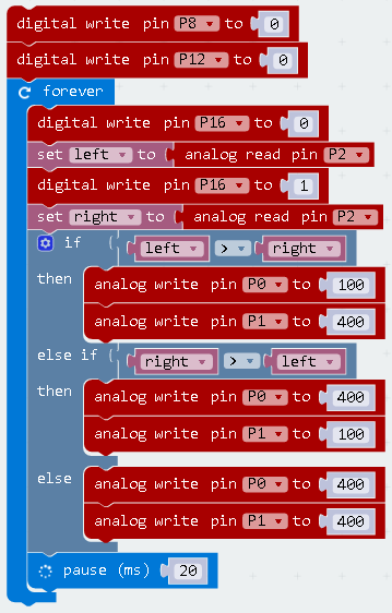
The JavaScript for this is,
let right = 0
let left = 0
pins.digitalWritePin(DigitalPin.P8, 0)
pins.digitalWritePin(DigitalPin.P12, 0)
basic.forever(() => {
    pins.digitalWritePin(DigitalPin.P16, 0)
    left = pins.analogReadPin(AnalogPin.P2)
    pins.digitalWritePin(DigitalPin.P16, 1)
    right = pins.analogReadPin(AnalogPin.P2)
    if (left > right) {
        pins.analogWritePin(AnalogPin.P0, 100)
        pins.analogWritePin(AnalogPin.P1, 400)
    } else if (right > left) {
        pins.analogWritePin(AnalogPin.P0, 400)
        pins.analogWritePin(AnalogPin.P1, 100)
    } else {
        pins.analogWritePin(AnalogPin.P0, 400)
        pins.analogWritePin(AnalogPin.P1, 400)
    }
    basic.pause(20)
})
Challenges
- Have the robot wake up when it detects a big change in light on either sensor. Start with a pause block to give you time to turn out the lights after setting up the robot. You will want 1000 for each second you need. Then, assign a reading from the sensors to a variable. Use a while loop to repeatedly take readings from the sensors while they remain below a threshold. After this, make the robot do something loud and bright.
- The example program is far from perfect. With a little tweaking, you can get better responses from the torch remote control if you have a small dead zone, a tolerance that allows you to move in a straight line more easily. In the loop, you could make the first clause of the if statement check if abs(lft - rgt) is less than the size of the dead zone and move forwards if it is. Try a number like 50 to start with and vary until you see if the effect work with your light source and conditions. You can also think more carefully about how much you want to turn the vehicle. You can experiment with the kinds of turn that you want the robot to make.
- What effect does the light from the neopixels have on the light sensors?