Other
Arduino - LED Projects
Arduino - Buzzer Projects
Arduino - Midi Projects
Arduino - Microview
Arduino - Other Projects
Arduino - Visual Basic.NET
Arduino - Tim's Projects
Arduino - Links
![]()


LED VU Meter
Introduction
A VU (Volume Unit) meter is a device designed to represent the level of an audio signal in equipment used for recording and playback. A true VU meter adheres to certain standards. This project is not concerned with those standards. The aim is to make a simple light show based on the sound levels being picked up by a microphone.
You Will Need
- 1 x Electret Microphone Amplifier - MAX4466
- 8 x LEDs
- 8 x 330 Ohm Resistors
- Jumper Wires
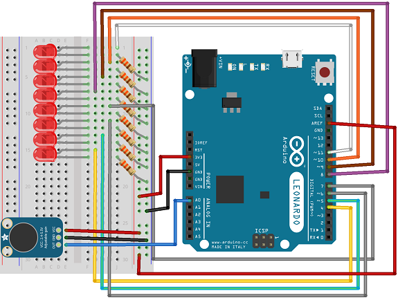
Making The Circuit
Take care with the way the power is connected here. The red cables in the diagram are the power supply. The 3.3V supply is being used for the microphone because it provides better performance. The connection to the AREF pin is to allow the analog pins to operate at 3.3V rather than at 5V. There is a line of code in the sketch that ensures this. If the Arduino you are using operates at 3.3V, then the connection and that line of code can be removed.
Programming The Arduino
Most of the code for this project is based on this tutorial from Adafruit, LED Ampli-Tie. The code has been adjusted (or butchered) to work with single colour LEDs. The original code is from a lovely e-textile project and uses chainable RGB LEDs. This version uses the microphone-specific parts of that code and makes the changes needed to use plain old LEDs.
#define N_PIXELS  8  // Number of LEDs

#define MIC_PIN   A0  // Microphone is attached to this analog pin

#define DC_OFFSET  0  // DC offset in mic signal - if unusure, leave 0

#define NOISE     10  // Noise/hum/interference in mic signal

#define SAMPLES   60  // Length of buffer for dynamic level adjustment

#define TOP       (N_PIXELS + 2) // Allow dot to go slightly off scale

#define PEAK_FALL 40  // Rate of peak falling dot

const int led[] = {4,5,6,7,8,9,10,11};

byte

peak      = 0,      // Used for falling dot

dotCount  = 0,      // Frame counter for delaying dot-falling speed

volCount  = 0;      // Frame counter for storing past volume data

int

vol[SAMPLES],       // Collection of prior volume samples

lvl       = 10,      // Current "dampened" audio level

minLvlAvg = 0,      // For dynamic adjustment of graph low & high

maxLvlAvg = 512;


void setup() {

  analogReference(EXTERNAL);

  memset(vol, 0, sizeof(vol));

  for(int i=0; i<N_PIXELS; i++)

  {

    pinMode(led[i],OUTPUT);

  }

}


void loop()

{

  uint8_t  i;

  uint16_t minLvl, maxLvl;

  int n, height;

  n   = analogRead(MIC_PIN);       // Raw reading from mic

  n   = abs(n - 512 - DC_OFFSET); // Center on zero

  n   = (n <= NOISE) ? 0 : (n - NOISE);     // Remove noise/hum

  lvl = ((lvl * 7) + n) >> 3;    // "Dampened" reading (else looks twitchy)


  // Calculate bar height based on dynamic min/max levels (fixed point):

  height = TOP * (lvl - minLvlAvg) / (long)(maxLvlAvg - minLvlAvg);


  if(height < 0L)       height = 0;      // Clip output

  else if(height > TOP) height = TOP;

  if(height > peak)     peak   = height; // Keep 'peak' dot at top


  for(i=0; i<N_PIXELS; i++)

  {

    if(i < height)

    {

      digitalWrite(led[i], HIGH);

    }

    else

    {

      digitalWrite(led[i], LOW);

    }

  }

  if(peak > 0 && peak <= N_PIXELS-1)

  {

    // colour peak dot

  }

  if(++dotCount >= PEAK_FALL) { //fall rate


    if(peak > 0) peak--;

    dotCount = 0;

  }

  vol[volCount] = n;   // Save sample for dynamic leveling

  if(++volCount >= SAMPLES) volCount = 0; // Advance/rollover sample counter

  // Get volume range of prior frames

  minLvl = maxLvl = vol[0];

  for(i=1; i<SAMPLES; i++) {

    if(vol[i] < minLvl)      minLvl = vol[i];

    else if(vol[i] > maxLvl) maxLvl = vol[i];

  }

  if((maxLvl - minLvl) < TOP) maxLvl = minLvl + TOP;

  minLvlAvg = (minLvlAvg * 63 + minLvl) >> 6; // Dampen min/max levels

  maxLvlAvg = (maxLvlAvg * 63 + maxLvl) >> 6; // (fake rolling average)

}
Challenges
The main effect of the project is to get some LEDs coming on and off in response to sound near the microphone. As stated earlier, this is not adhering to any standards. Changing the way the lights are laid out, as well as the colours, you can make a pretty cool set of mini disco lights. Clearly, a bar graph would be a suitable component for this display.
A shift register would be a more efficient way of doing this particular circuit and a reasonable challenge. The advantage of using a shift register would be the freeing up of some more pins. Using PWM, you could add brightness adjusting to a few extra LEDs.
In the code, there is a place for dealing with the peak dot. This is the peak level and needs to be coloured differently to the other LEDs to make the display look a little more interesting. If this project were set up with bi-colour LEDs configured to run off a single pin each, this could be done.