Other
Arduino - LED Projects
Arduino - Buzzer Projects
Arduino - Midi Projects
Arduino - Microview
Arduino - Other Projects
Arduino - Visual Basic.NET
Arduino - Tim's Projects
Arduino - Links
![]()


RGB LED
Introduction
The RGB LED allows you to display a full range of colours using a single LED. The one that comes with the Sparkfun Inventor's Kit is a common cathode RGB. This means that it has a single negative pin for all 3 of its LEDs.
You Will Need
- 1x RGB LED
- 3 x 330 Ohm Resistors
- Jumper Wires
Making The Circuit
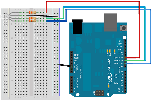
The RGB LED has 4 pins. The longest of these is the cathode and is connected to GND. If you place that on Row 2 of the breadboard, the red pin will be on Row 1, the green pin on Row 2 and the blue pin on Row 3.
Programming The Arduino
To start off, we can use digitalWrite statements to make the LED turn from red to green to blue.
int redPin = 11;

int greenPin = 10;

int bluePin = 9;

void setup()

{

  pinMode(redPin, OUTPUT);

  pinMode(greenPin, OUTPUT);

  pinMode(bluePin, OUTPUT);

}


void loop()

{

  showPrimary();

}


void showPrimary()

{

  //red

  digitalWrite(redPin, HIGH);

  digitalWrite(greenPin, LOW);

  digitalWrite(bluePin, LOW);

  delay(1000);

  //green

  digitalWrite(redPin, LOW);

  digitalWrite(greenPin, HIGH);

  digitalWrite(bluePin, LOW);

  delay(1000);

  //blue

  digitalWrite(redPin, LOW);

  digitalWrite(greenPin, LOW);

  digitalWrite(bluePin, HIGH);

  delay(1000);

}
The beauty of the RGB LED is when we use analogWrite to get the different parts of the component to light at different intensities. The following code adds a subroutine called showRGB() to display the colour of your choice. The code in the loop will display a lovely violet.
int redPin = 11;

int greenPin = 10;

int bluePin = 9;

void setup()

{

  pinMode(redPin, OUTPUT);

  pinMode(greenPin, OUTPUT);

  pinMode(bluePin, OUTPUT);

}


void loop()

{

  showRGB(23,0,22);

}


void showPrimary()

{

  //red

  digitalWrite(redPin, HIGH);

  digitalWrite(greenPin, LOW);

  digitalWrite(bluePin, LOW);

  delay(1000);

  //green

  digitalWrite(redPin, LOW);

  digitalWrite(greenPin, HIGH);

  digitalWrite(bluePin, LOW);

  delay(1000);

  //blue

  digitalWrite(redPin, LOW);

  digitalWrite(greenPin, LOW);

  digitalWrite(bluePin, HIGH);

  delay(1000);

}


void showRGB(int r, int g, int b)

{

  analogWrite(redPin, r);

  analogWrite(greenPin, g);

  analogWrite(bluePin, b);

}
Challenges
The RGB LED is crying out to be used as a traffic light. You only need to work out how to display amber (orange) and then you can cycly through the whole routine.
Work out or find out the RGB values of the colours of the rainbow. Program the Arduino to display a cycle of these colours with a small delay between each one.
Now think about some other ways to change the colour. A smooth gradient of colour change would be lovely. Perhaps instead, you want to make the colours change randomly between each delay.