Other
Arduino - LED Projects
Arduino - Buzzer Projects
Arduino - Midi Projects
Arduino - Microview
Arduino - Other Projects
Arduino - Visual Basic.NET
Arduino - Tim's Projects
Arduino - Links
![]()


Binary Clock
Introduction
In this project, 16 LEDs are used to represent the time in binary. The time is read from a Real Time Clock breakout board - the same one used in the Digital Clock page.
The binary clock uses 4 place values for the hour (12hr format), 6 place values for the minutes, and 6 for the seconds.
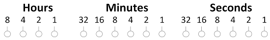
So the following pattern...
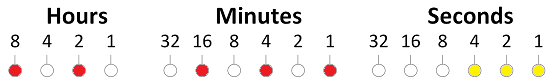
... makes the time, 8+2 = 10 hours, 16 + 4 + 1 = 21 minutes, 4+2+1 = 7 seconds.
You Will Need
- DS1307 Breakout Board & RTC
- 2 x 74HC595 Shift Registers
- 16 x LEDs
- 16 x 330 Ohm Resistors
- Jumper Wires
- 2 Full Size Breadboards
Making The Circuit
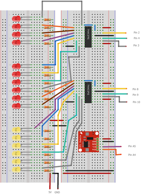
Take care with this one, there are a lot of things to get connected. The Arduino isn't shown in this diagram. The text labels show the pin connections - the connections to the shift registers are to digital pins.
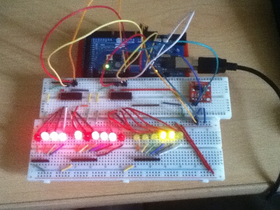
Here is a blurry photograph of the binary clock circuit set up on an Arduino Mega. There are some minor differences to the diagram to account for the differences between the Uno and the Mega. Some of the components (eg resistors) are also slightly different. However, it works just like the one in the diagram.
Programming The Arduino
The tricky part of this code is to create the correct binary pattern. The first shift register controls the 4 LEDs that make the hours as well as 4 of the LEDs that make up the minutes. The second shift register does the other 2 LEDs of the minutes as well as all of the seconds.
Because of the number of places where a faulty or missing connection can prevent this from working, it's worth just checking that you can light all of the LEDs properly. With the rest of the code as below, replace the loop with the following lines to make sure that all of the LEDs can be lit,
  writeByte(255,1);

  writeByte(255,2);
The main program,
#include <Wire.h>

#include "RTClib.h"


RTC_DS1307 RTC;

int datapin = 2;

int clockpin = 3;

int latchpin = 4;

int datapin2 = 8;

int clockpin2 = 9;

int latchpin2= 10;


void setup()

{

  Serial.begin(57600);

  Wire.begin();

  RTC.begin();


  if (! RTC.isrunning()) {

    Serial.println("RTC is NOT running!");

    // following line sets the RTC to the date & time this sketch was compiled

    //RTC.adjust(DateTime(__DATE__, __TIME__));

  }


  pinMode(datapin, OUTPUT);

  pinMode(clockpin, OUTPUT);

  pinMode(latchpin, OUTPUT);

  pinMode(datapin2, OUTPUT);

  pinMode(clockpin2, OUTPUT);

  pinMode(latchpin2, OUTPUT);

}


void loop()

{


  DateTime now = RTC.now();

  // All used for checking the time of the clock

  // This section can be removed when everything is working

  Serial.print(now.day(), DEC);

  Serial.print('/');

  Serial.print(now.month(), DEC);

  Serial.print('/');

  Serial.print(now.year(), DEC);

  Serial.print(' ');

  Serial.print(now.hour(), DEC);

  Serial.print(':');

  Serial.print(now.minute(), DEC);

  Serial.print(':');

  Serial.print(now.second(), DEC);

  Serial.println();

  // End of section that can be removed


  int mins = now.minute();

  int secs = now.second();

  int hr = now.hour();

  // convert to 12 hour time

  if (hr>12)

  {

    hr = hr-12;

  }


  // variables to describe pattern of on lights

  byte data1 = 0;

  byte data2 = 0;


  // encode the time

  // hr = 1st four bits

  for (int i =0;i<4;i++)

  {

    if (bitRead(hr,i)==1)

    {

      bitWrite(data1,3-i,1);

    }

  }

  // mins on the first shift register

  for (int i =2;i<6;i++)

  {

    if (bitRead(mins,i)==1)

    {

      bitWrite(data1,9-i,1);

    }

  }

  // remaining mins LEDs

  for (int i =0;i<2;i++)

  {

    if (bitRead(mins,i)==1)

    {

      bitWrite(data2,1-i,1);

    }

  }

  // seconds

  for (int i =2;i<8;i++)

  {

    if (bitRead(secs,i-2)==1)

    {

      bitWrite(data2,9-i,1);

    }

  }

  // output the information

  writeByte(data1,1);

  writeByte(data2,2);

  // a brief pause

  delay(500);


}


void writeByte(byte data, byte set)

{

  int d,c,l;

  if (set==1)

  {

    d = 2;

    c = 3;

    l = 4;

  }

  else if (set==2)

  {

    d = 8;

    c = 9;

    l = 10;

  }

  shiftOut(d, c, MSBFIRST, data);

  // toggle the latch pin so that the data appears as an output

  digitalWrite(l, HIGH);

  digitalWrite(l, LOW);

}
Challenges
The clock works but it has some missing features and a few flaws. The first is that the RTC does not adjust for clock changes. These happen at predicatable times and could be accounted for in this prototype.
It would be useful to be able to set the time on the clock. A couple of push buttons and some nice code and you could set this up.
A configurable alarm could be made if you added a Piezo buzzer.
The next thing you might consider is the power usage. With the LEDs on all of the time, this project would quickly take all of the power from a battery. That's fine if it's mains-powered but not so good if you want some portability. Adjusting the program so that time is displayed when a pushbutton is pressed would help address this.
Finally, this would make an excellent soldering project if you have your own components, a soldering iron and some perfboard.