Other
Arduino - LED Projects
Arduino - Buzzer Projects
Arduino - Midi Projects
Arduino - Microview
Arduino - Other Projects
Arduino - Visual Basic.NET
Arduino - Tim's Projects
Arduino - Links
![]()


Touch Input
Introduction
This project explains how to connect the Arduino to the Touch Input integrated circuit that is sold by Hobbytronics. It is an 8-pin DIL chip with 2 independent touch inputs that can be configured as momentary or latching switches.
You Will Need
- 1 x Touch IC
- 2 x 1M Ohm Resistors
- Something conductive to make the switch
- Jumper Wires
Making The Circuit
The pin layout for the ic is as follows,
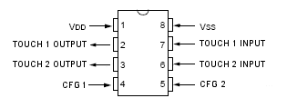
VDD is the 5V pin. VSS is GND. The CFG pins are config pins that set each switch into latching or momentary mode. If the pin is connected to GND, the switch works in momentary mode. If the CFG pin is connected to 5V, the switch works in latching mode. You use a latching switch when you want to use a single press of a switch to toggle the state of the circuit - like a start/stop switch or a pause button. A momentary switch is used when you want to do something whilst the switch is pressed and not do it when it isn't.
This diagram shows a circuit for latching mode. Notice that the two CFG pins are connected together and then to 5V. If you connect them to GND instead, you change the switching mode to momentary.
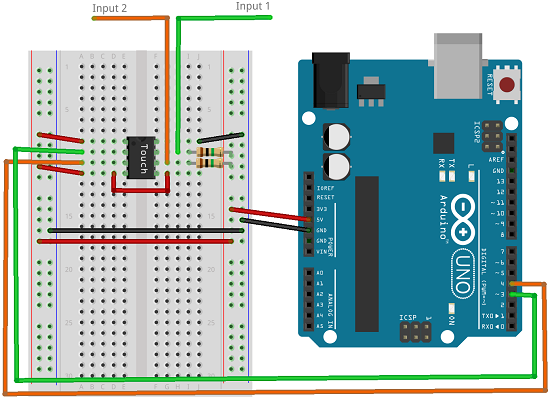
The input pins can be connected to something conductive like Play-Doh or a piece of metal. Alternatively, use relatively short jumper wires and touch the ends to activate the switches.
Make sure that the two resistors are not touching one another. Move one or both to a separate part of the breadboard if you can't reliably keep them apart.
Programming The Arduino
This is a simple sketch using the Serial monitor to see the output from the circuit.
int inp1 = 3;

int inp2 = 4;

void setup()

{

  Serial.begin(9600);

  pinMode(inp1, INPUT);

  pinMode(inp2, INPUT);

}

void loop()

{

  int state1 = digitalRead(inp1);

  int state2 = digitalRead(inp2);

  Serial.print(state1);

  Serial.print(",");

  Serial.println(state2);

  delay(50);

}
Once you have uploaded the sketch, open the serial monitor and you should see two numbers separated by a comma. Touch the switches and you should see them change from 1 to 0 and vice versa.
Challenges
Clearly, the most obvious challenge is to replace the buttonage in an existing project with some exciting touch input. Failing that, a Play-Doh buzzer piano would be pretty cool.
This is not the only method you can use to get touch input in an Arduino circuit. An alternative method is to use an integrated circuit with more inputs. The MPR121 touch-sensitive controller is pretty good and allows 12 electrodes to be used as touch inputs. A handful of different breakout boards have been made for this. Do check out the operating voltage before purchase and use though. A more DIY approach is to look into the Capsense library or find out about resistive switching.