Other
Arduino - LED Projects
Arduino - Buzzer Projects
Arduino - Midi Projects
Arduino - Microview
Arduino - Other Projects
Arduino - Visual Basic.NET
Arduino - Tim's Projects
Arduino - Links
![]()


7 Segment LED
Introduction
Seven segment displays are widely used in electronic displays to display numerals. This page is concerned with a specific device, the Sparkfun single digit 7 segment display.
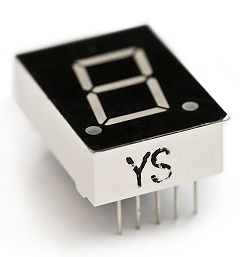
The device has 10 pins arranged in 2 rows of 5 pins at the top and bottom of the display. The middle pin of each row is an anode (positive) pin. We can choose which one of these to use. This is a common anode display. That means that there is one anode. To light up a segment we connect its cathode to a digital pin and drive that pin low, grounding the circuit. To turn off a segment, we drive its cathode high.
You Will Need
- 1 x 7 Segment Common Anode Display
- 8 x 330 Ohm Resistors
- Jumper Wires
- 6 Column Breadboard
This particular module is a little large for a standard breadboard. Standard breadboards have 2 sections of 5 columns. This leaves little space to attach the jumpers. If you can get hold of a 6 column breadboard, the display will fit nicely and there will be space to connect jumpers.
Making The Circuit
Here is a pin diagram for the display,
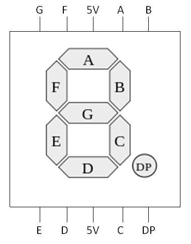
The letters used to label each segment are standard. It will help when using references for character displays if we use the same order.
Connect one of the pins labelled 5V to the 5V pin on the Arduino.
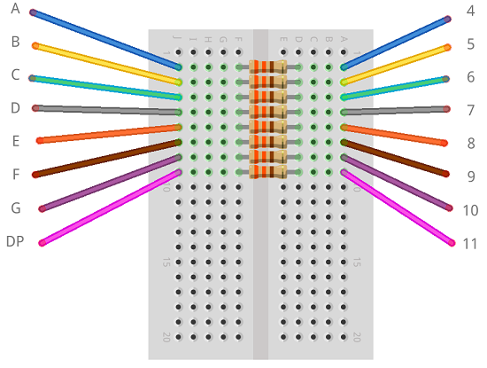
Place the resistors on a separate part of your breadboard, spanning the middle section and connect them as indicated in the diagram below,
Programming The Arduino - Testing Connections
The following code can be used to test the connections. An array is used to identify the cathodes connected to the digital pins. The setup procedure drives each of these pins HIGH so that the sketch begins with all of the LEDs unlit. The loop drives each of the cathodes LOW in turn so that we can check that the connections are in the order specified in the diagrams earlier on this page.
int ledpins[] = {4,5,6,7,8,9,10,11};


void setup()

{

  for (int i =0;i<8;i++)

  {

    pinMode(ledpins[i],OUTPUT);

    digitalWrite(ledpins[i], HIGH);

  }

}


void loop()

{

  for (int i =0;i<8;i++)

  {

    digitalWrite(ledpins[i], LOW);

    delay(500);

    digitalWrite(ledpins[i], HIGH);

    delay(500);

  }

}
Programming The Arduino - Displaying Numbers
The following sketch counts from 0 - 9 repeatedly.
int ledpins[] = {4,5,6,7,8,9,10,11};

byte digits[] = {B11111100,B01100000,B11011010, B11110010,B01100110,B10110110,B10111110,B11100000,B11111110,B11110110};


void setup()

{

  for (int i =0;i<8;i++)

  {

    pinMode(ledpins[i],OUTPUT);

    digitalWrite(ledpins[i], HIGH);

  }

}


void loop()

{

  for (int i =0;i<10;i++)

  {

    displayDigit(i);

    delay(1000);

    alloff();

    delay(500);

  }

}


void displayDigit(int digit)

{

  for (int i =0;i<8;i++)

  {

    digitalWrite(ledpins[i],!bitRead(digits[digit],7-i));

  }

}


void alloff()

{

  for (int i =0;i<8;i++)

  {

    digitalWrite(ledpins[i], HIGH);

  }

}
The digits array has been defined using binary. I have used a 1 where the segment is supposed to be lit and a 0 when not. The last digit is always a 0 - it represents the decimal point that we are not using in this sketch.
The alloff() procedure simply makes sure that all of the cathodes are driven high and all segments are off.
The displayDigit() procedure is used to turn on the correct segments for the digit that needs to be displayed. The bitread function reads the bits of the binary number, starting with the rightmost bit. That is why the 7-i is used. When using the digitalWrite() statement, we can write a 1 when we want HIGH and a 0 when we want LOW. This is the opposite of how our binary numbers are working. The ! operator takes care of that by inverting the value for us.
Challenges
You could use this component as the display for an electronic die. The LED dice page in this section shows how to generate the random numbers, you could easily adapt this sketch to do the same.
Numbers from 0 - 9 can be displayed in binary using only 4 LEDs. You could design a project that displayed the binary values of the numbers 0 - 9. More interesting would be a project which tested the user on the binary numbers by allowing them to create a binary pattern to match the display using some pushbuttons.
Other characters can be displayed using 7 segments. There are conventions for the letters A-F which would allow hexadecimal to be used. Using 4 LEDs, you can represent the same value in binary.
Any project where you have this many connections from a device to digital pins is crying out to be implemented using a shift register. With the shift register, you could write the values to the display more efficiently too. If you get the digits array just right, you can make it very easy to write the number/character on the display.