Other
Arduino - LED Projects
Arduino - Buzzer Projects
Arduino - Midi Projects
Arduino - Microview
Arduino - Other Projects
Arduino - Visual Basic.NET
Arduino - Tim's Projects
Arduino - Links
![]()


Controlling The Fade
Introduction
In this project we will add a trimmer potentiometer and use it as a brightness controller for the LED.
You Will Need
- 1 x LED
- 1 x 330 Ohm Resistor
- 10K Trimmer Potentiometer
- Jumper Wires
The 10K trim pot that comes with the Sparkfun Inventor's Kit looks like this,
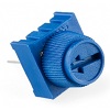
The potentiometer is a variable resistor. Turning the knob on the potentiometer changes the amount of resistance the component brings to that part of the circuit. This can be read as a change in voltage on one of the analog pins of the Arduino and will return a number from 0 to 1023.
Making The Circuit
The diagram shows how the circuit should look.
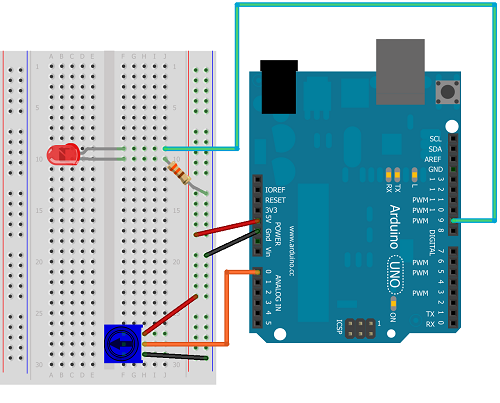
The middle pin of the trimmer is the pin we want to read from. This will be connected to one of the analog pins on the Arduino. One of the other pins should be connected to 5V, the other to GND. Resistors can be connected in whichever direction you like. With a resistor like the one you use to connect the LED to GND, it doesn't make any difference which way around you place it. Normally people have all of their resistors facing in one direction so that the circuit is easier to understand. If you swap the 5V and GND connections on the trimmer, you change which way you have to turn the knob to make the LED bright.
Programming The Arduino
Here is the code you will need for the basic control of this circuit,
int ledPin = 9;

int potPin = 0;


void setup()

{


}


void loop()

{

  // read from the potentiometer

  int potValue = analogRead(potPin);

  // convert the reading to a value in the range we want

  potValue = int(potValue/4);

  // write that value to the led pin

  analogWrite(ledPin, potValue);

}
Notice that, because we are using analogRead and analogWrite, we do not need to set the pin mode for the two pins we are using.
The value that is read from the trimmer needs to be divided by 4 to make sure it is no greater than 255.
Exploring A Little
Try swapping the 5V and GND connections to the potentiometer, this should affect which way you have to turn the knob to make the LED bright or dim.
Challenge - 1
Connect another LED to pin 10 on the Arduino. Start by making to so that both LEDs fade and brighten in the same way. Then change the code so that, as one of the LEDs gets brighter, the other one fades.
Challenge - 2
Look back at the first page of this section (Single LED Project). Find the example code that you used to make the LED blink. Adapt the code you have so that you can use the trimmer potentiometer to vary the speed of the blinking. Remember that you will be using digitalWrite statements so need to establish the pin as an output pin in the setup procedure. You can use the raw values from the trimmer as the delay to vary the delay from 0 to 1023 or can use statements to convert that number to something different. Observe the effect you get when the delay is really small.