Other
Arduino - LED Projects
Arduino - Buzzer Projects
Arduino - Midi Projects
Arduino - Microview
Arduino - Other Projects
Arduino - Visual Basic.NET
Arduino - Tim's Projects
Arduino - Links
![]()


LED Dice
Introduction
This project shows how to make your Arduino act like a single 6-sided die using LEDs and a button.
You Will Need
- 7 x LEDs
- 7 x 330 Ohm Resistors
- 1 x Pushbutton
- 1 x 10 KOhm Resistor
- Jumper Wires
Making The Circuit
It's hard to show the layout of the LEDs in a diagram without them covering each other. You need a layout that gives you a pattern of 7 dots. In the following image, you can see how the LEDs have been placed into a section of the breadboard,
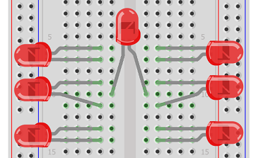
You have to bend the pins a little to place them. Don't bend them too much if they need to be used again for another project.
Other Things To Do
- Add 330 Ohm resistors connecting each of the shorter pins (negative) to GND on the breadboard.
- Connect a pushbutton up to another part of the breadboard (look at the LED pushbutton project to see how to do that). Use pin 8.
- Connect up the 5V and GND rails of the breadboard to the correct pins on the LED.
- Connect the LEDs to Arduino pins 1 - 7 using the following order,
| 4 | 1 | |
| 5 | 7 | 2 |
| 6 | 3 |
Programming The Arduino - Test LED Connections
Because the LEDs are a little close to one another and there are a few of them, it's worth just checking that they are all properly connected. The following code will do that for you,
int ledPin[] = {1,2,3,4,5,6,7};


void setup()

{

  for (int i = 0;i<=6;i++)

  {

    pinMode(ledPin[i], OUTPUT);

  }

}


void loop()

{

  for (int i = 0;i<=6;i++)

  {

    digitalWrite(ledPin[i], HIGH);

  }

  delay(500);

    for (int i = 0;i<=6;i++)

  {

    digitalWrite(ledPin[i], LOW);

  }

  delay(500);

}
All 7 LEDs should blink on and off.
Programming The Arduino - Make It Happen
int ledPin[] = {1,2,3,4,5,6,7};

int rollValues[] = {0,64,33,97,45,109,63};

int buttonPin = 8;

int previousState = 1;

void setup()

{

  for (int i = 0;i<=6;i++)

  {

    pinMode(ledPin[i], OUTPUT);

  }

  pinMode(buttonPin, INPUT);

  randomSeed(analogRead(0));

}


void loop()

{

  int buttonState = digitalRead(buttonPin);

  if (buttonState!=previousState && buttonState==LOW)

  {

    roll();

    delay(10);

  }

  previousState = buttonState;

}


void roll()

{

  int thisroll;

  for (int i =0;i<20;i++)

  {

    thisroll = random(1,7);

    showBinary(0);

    delay(50);

    showBinary(rollValues[thisroll]);

    delay(50);


  }


}


void showBinary(byte numToShow)

{


  for (int i =0;i<7;i++)

  {

    if (bitRead(numToShow, i)==1)

    {

      digitalWrite(ledPin[i], HIGH);

    }

    else

    {

      digitalWrite(ledPin[i], LOW);

    }

  }

}
Key Things To Notice
- A Random Seed is set for the random number generator by reading the 'noise' from one of the unconnected pins.
- A showBinary function is adapted from one of the earlier projects to allow us to use a single byte to represent each pattern on the die.
- The roll() procedure cycles quickly through 20 different numbers and stops on the last one.
Challenges
This project takes up 8 pins. With a shift register, the code would be simpler and only 4 pins would be needed in total.
Using a similar principle to this project, you could lay out a load of LEDs (say 12) in a 4x3 grid. If you treat each column of 4 LEDs as a 4-bit binary number, you could find an efficient way to write patterns to the grid. With 5 rows of 3, you can display digits quite reasonably.