Other
Arduino - LED Projects
Arduino - Buzzer Projects
Arduino - Midi Projects
Arduino - Microview
Arduino - Other Projects
Arduino - Visual Basic.NET
Arduino - Tim's Projects
Arduino - Links
![]()


Single LED Project
Introduction
This is as good a starting point as I can think of for starting with the Arduino. It involves using the Arduino to turn an LED on or off as you see fit. It's about as simple as a circuit can get and as little programming as might be required.
You Will Need
- 1 x LED
- 1 x 330 Ohm Resistor
- Jumper Wires
NB Different LEDs require different resistors. The ones that come in the Sparkfun Inventor's Kit are 5mm LEDs which will need a 330ohm resistor to ensure the right kind of brightness and to look after the LED. Different LEDs may work better with a different resistor. The datasheet or specification for the particular LED you are using will normally state the minimum and maximum currents and voltages needed to power the LED without burning it out. When you buy packs of LEDs, they often come with the resistors that are most suitable for them.
Making The Circuit
The diagram shows how the circuit should look.
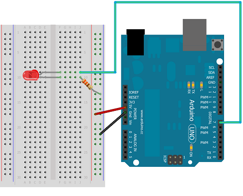
Start by making the connections to the positive and ground rails of the breadboard. In the diagram, these are shown with red and black wires respectively. All of the points are connected vertically on this part of the breadboard. The connection from 5V is not really needed in this circuit but we may as well put it there as we will be doing this in quite a lot of our later circuits. The connection from GND is going to be used.
Next place the LED. One of the pins on the LED will be longer than the other. This is the anode or positive pin. We will be connecting this to Arduino pin 7 with a jumper wire. LEDs have to be placed the correct way around or they won't work. Unlike the positive and ground lines at the side of the breadboard, the pins in the centre parts of the breadboard are connected horizontally. This is why the two pins of the LED need to be connected to different rows.
Now add the resistor so that it connects the negative pin (cathode) of the LED to GND. This completes the circuit and will make it possible to light the LED.
Connect the USB cable to the Arduino and plug it into a USB slot on the computer.
Programming The Arduino
With the Arduino plugged in, you need to make sure that the Arduino software can 'see it'. First click on Tools & Board on the menu. Check that your Arduino board is selected. If you are using the Sparkfun Inventor's Kit, you should select the Arduino Uno. Now go to Tools & Serial Port on the menu. You have to make sure the software knows which port your Arduino is connected to. If there is more than one COM port, your Arduino is normally connected to the one with the larger number - the other ports will probably be used for a mouse or a keyboard depending on which peripherals you have connected.
Copy and paste the following code into the IDE.
int ledPin = 7;


void setup()

{

 pinMode(ledPin, OUTPUT);

}


void loop()

{

 digitalWrite(ledPin, HIGH);

}
Before the code can be used, it needs to be checked and then uploaded to the chip on the Arduino. We do this using the two buttons shown in the image,
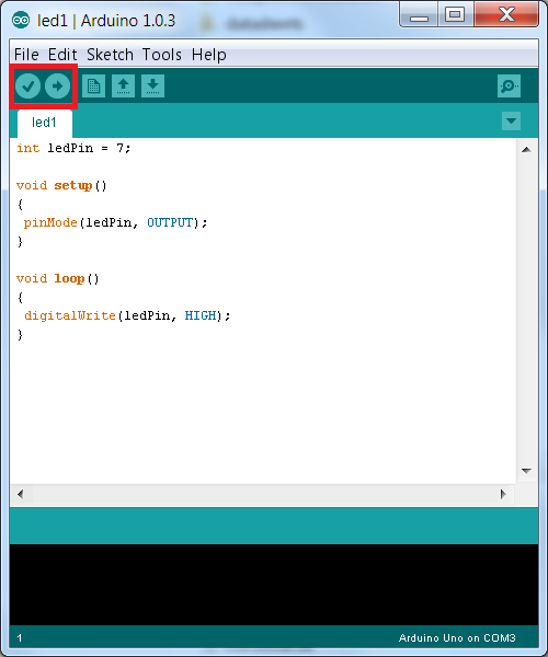
The first button (the tick) is used to verify and compile the code so it is ready for upload. Press this button and obvious typing errors will be shown to you at the bottom of the window. The next button (right arrow) will upload the compiled code to the Arduino.
When you upload the code from above, the LED should come on. If your LED doesn't come on, check the code and check the wiring, you have either made or mistake or the LED you have used is broken.
Understanding The Code
Let's take a moment to understand the instructions that we have just given to the Arduino. Arduino programs, called sketches have some minimum requirements. The following two procedures are always needed,
void setup()

{


}


void loop()

{


}
The setup procedure is used for code that needs to be executed when the Arduino first receives power. In our code we have used a pinMode statement to define pin 7 on the Arduino as an output pin.
The loop procedure, as its name suggests, is executed repeatedly. When the Arduino chip has executed all of the instructions in the loop procedure it returns to the first statement in the loop and starts all over again. In our code, we have used a digitalWrite statement to cause pin 7 to output a high voltage (and power up the LED). Clearly we only need to do this once, but since it is only one statement, nothing happens if we have it repeated.
Adapting The Code - Turn The LED Off
Making the LED not light is pretty simple. Change the digitalWrite statement so that it sends LOW to the pin. It's a strange thing to do since we could get the same effect by simply not using any components.
Adapting The Code - Blinking
The following code will make the LED blink on and off,
int ledPin = 7;


void setup()

{

  pinMode(ledPin, OUTPUT);

}


void loop()

{

  digitalWrite(ledPin, HIGH);

  delay(1000);

  digitalWrite(ledPin, LOW);

  delay(1000);

}
The new statement here is the delay statement. The number in the brackets is the number of milliseconds that we want the Arduino to wait before executing the next statement. Here we have used 1000, so a delay of a second. You can change the number to achieve a different effect.
Adapting The Code - Blink 5 Times
The following code adds a global variable d to keep track of how many times the LED has been switched on and off. At the start of the loop this variable is increased by 1. If it hasn't gone higher than 5, the LED is blinked on and off.
int ledPin = 7;

long d = 0;

void setup()

{

  pinMode(ledPin, OUTPUT);

}


void loop()

{

  d++;

  if (d<=5)

  {

    digitalWrite(ledPin, HIGH);

    delay(1000);

    digitalWrite(ledPin, LOW);

    delay(1000);

  }

}
Challenge
Find out the Morse code for your name. Use a combination of long and short delays to make the LED blink your name. Put a longer delay at the end of the message and then let it repeat your name over and over again.
About Morse Code
- Start by working out how long you are going to leave the LED on for a DOT. This is your dot length.
- The dash length should be 3 times the dot length.
- Between each dot or dash, there should be an inter-element gap of one dot length (where the LED is off).
- Between each complete letter, there should be a gap equal to the length of a dash (where the LED is off).
- Between each complete word, there should be a gap equal to 7 times the dot length (where the LED is off).
| Letter | Code |
|---|---|
| A | DOT DASH |
| B | DASH DOT DOT DOT |
| C | DASH DOT DASH DOT |
| D | DASH DOT DOT |
| E | DOT |
| F | DOT DOT DASH DOT |
| G | DASH DASH DOT |
| H | DOT DOT DOT DOT |
| I | DOT DOT |
| J | DOT DASH DASH DASH |
| K | DASH DOT DASH DOT |
| L | DOT DASH DOT DOT |
| M | DASH DASH |
| N | DASH DOT |
| O | DASH DASH DASH |
| P | DOT DASH DOT DASH |
| Q | DASH DASH DOT DASH |
| R | DOT DASH DOT |
| S | DOT DOT DOT |
| T | DASH |
| U | DOT DOT DASH |
| V | DOT DOT DOT DASH |
| W | DOT DASH DASH |
| X | DASH DOT DOT DASH |
| Y | DASH DOT DASH DASH |
| Z | DASH DASH DOT DOT |