Other
Arduino - LED Projects
Arduino - Buzzer Projects
Arduino - Midi Projects
Arduino - Microview
Arduino - Other Projects
Arduino - Visual Basic.NET
Arduino - Tim's Projects
Arduino - Links
![]()


Bubble Segment - Shift Register
Introduction
This project builds on the explanation on Tim's page, 7 Segment Bubble Display. You are advised to start there if you are just looking to get the bubble display working. In this project, a shift register is used to drive the anodes of the display, saving 5 digital pins that can be used for other components.
In Tim's project, the Sparkfun library is used to put the digits on the display. For this project, we'll need to go back to basics about how we get individual parts of the display to light up.
You Will Need
- 74HC595 Shift Register
- 7 Segment 4 Digit Bubble Display
- 8 x 1KOhm Resistors
- Loads of Jumpers
Making The Circuit
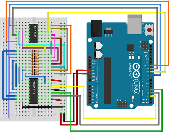
There's a lot of wiring going on here. If you start by connecting up the shift register and the resistors, you'll find it a bit easier. The wire colours in the diagram are abitrary, different colours to help pinpoint where each wire goes rather than any electrical significance.
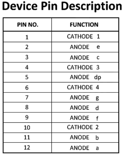
You might find it easier to connect the bubble display using this table from the datasheet.
The resistors are (from bottom up) connected to anodes A-G and the DP.
Programming The Arduino
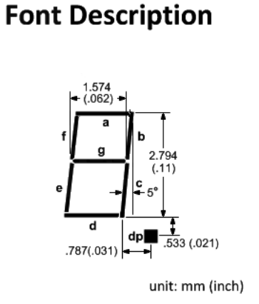
In order to display a digit, we first make the cathode for that digit LOW and the other 3 cathodes HIGH. Then we make the shift register drive the anodes of the segments we want to light HIGH. This process is repeated for each of the 4 digits. The following diagram from the datasheet may help you to understand the binary patterns in the code,
int datapin = 2;

int clockpin = 3;

int latchpin = 4;


int cathodes[] = {8,9,10,11};

byte digits[] = {

  0b11111100, // 0

  0b01100000, // 1

  0b11011010, // 2

  0b11110010, // 3

  0b01100110, // 4

  0b10110110, // 5

  0b10111110, // 6

  0b11100000, // 7

  0b11111110, // 8

  0b11110110 }; // 9


void setup()

{

  pinMode(datapin, OUTPUT);

  pinMode(clockpin, OUTPUT);

  pinMode(latchpin, OUTPUT);

  for (int i =0;i<4;i++)

  {

    pinMode(cathodes[i], OUTPUT);

  }

  cathodesHigh();

}


void loop()

{

    for (int i=0;i<4;i++)

    {

    cathodesHigh();

    digitalWrite(cathodes[i], LOW);

    writeByte(digits[i]+1);

    delay(1);

    }

}

void cathodesHigh()

{

  for (int i =0;i<4;i++)

  {

    digitalWrite(cathodes[i], HIGH);

  }

}

void writeByte(byte data)

{

  shiftOut(datapin, clockpin, LSBFIRST, data);

  // toggle the latch pin so that the data appears as an output

  digitalWrite(latchpin, HIGH);

  digitalWrite(latchpin, LOW);

}
Challenges
This sketch does all of the LED work in the main loop. Anything you add that changes the timing of this loop will affect the display. That can be fixed by using timers to do the work in the background. That way, as when you use the library, you write the numbers to the display once and then they remain there until you change them.
With another shift register, you could drive an extra display, making 8 digits. Since you'd now have 8 cathodes, you may as well add a third shift register and get the whole thing working off 3 digital pins. That leaves more than enough pins free for some serious buttonage.