Raspberry Pi Pico
MicroPython - Basics
MicroPython - More Involved
MicroPython - Pico W
MicroPython - micro:bit
MicroPython - Projects
CircuitPython - Some Basics
CircuitPython - HID Adventures
CircuitPython - Experiments
Other Pages
![]()


Raspberry Pi Pico
7-Segment LED
This page describes how to work with a single digit 7 segment LED display. Controlling one of these is relatively straightforward once you have made the right connections.
The display consists of 8 LEDs. A standard LED will usually have two pins. One of those pins is positive. We call this the anode and connect it to an output or power pin. I have connected it to 3V3 in my circuit. The other pin is negative. We call that the cathode and connect it to GND. We also use a resistor to limit the current going through the LED. In this circuit 100 Ohm resistors are used.
This display is called a common anode display. All of the LEDs anodes have been wired together. If we apply power through the anode, we can turn each LED on by writing a 0 or LOW signal to the segment's cathode. Writing a 1 turns it off.
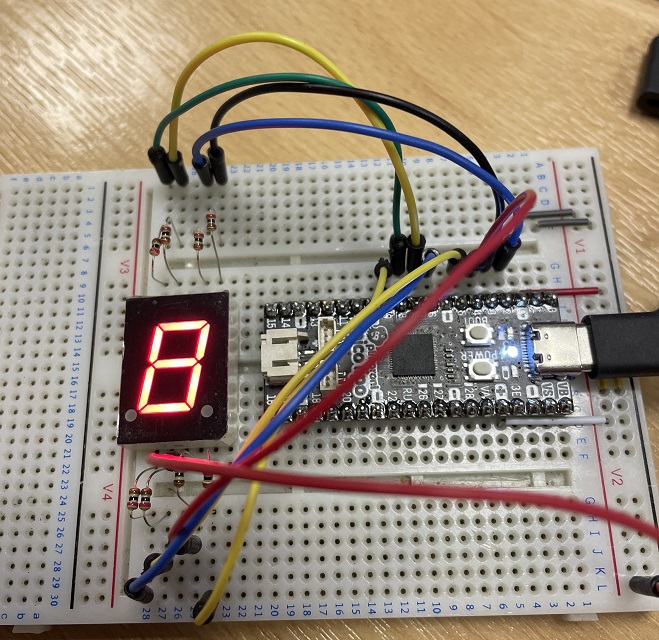
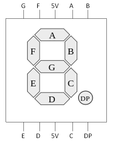
These displays are always a little bit of a mission to set up. There are lots of wires and the pins are often placed to allow easy routing to the LEDs in the package to keep it compact. This is the pinning diagram from the datasheet that we will be working from,
If you compare the photograph to the pinout diagram, you can see that I started by placing a resistor on each of the cathodes. I then took a wire and connected each of the cathodes in order to pins 2 - 9.
The code is relatively simple. The digits list is a list of integers whose binary representation has the correct LEDS lit for the digit in that position in the list. I use a list comprehension to quickly convert these numbers into a list of 1s and 0s.
from machine import Pin
from time import sleep

cats = [2, 3, 4, 5, 6, 7, 8, 9]
digits = [0b00000011,0b10011111,0b00100101, 0b00001101,0b10011001,
0b01001001,0b01000001,0b00011111,0b00000001,0b00011001]

pins = [Pin(i, Pin.OUT) for i in cats]

def WriteDigit(d):
    bits = [digits[d] >> i & 1 for i in range(7,-1,-1)]
    for p in range(8):
            pins[p].value(bits[p])

while True:
    for i in range(10):
        WriteDigit(i)
        sleep(1)