Raspberry Pi Pico
MicroPython - Basics
MicroPython - More Involved
MicroPython - Pico W
MicroPython - micro:bit
MicroPython - Projects
CircuitPython - Some Basics
CircuitPython - HID Adventures
CircuitPython - Experiments
Other Pages
![]()


Raspberry Pi Pico
Charlieplexing LEDs
Multiplexing is the name given to the techniques used to reduce the number of pins required to drive a component. Charlieplexing is a multiplexing technique that takes advantage of the microcontroller's ability to puts digital pins into 3 states (high, low, input) in order to dramatically reduce the number of pins required to drive a given number of LEDs. The technique is named after its inventor, Charlie Allen, who proposed the technique in the mid 90's whilst working at Maxim Integrated Products.
In order to achieve this, the LEDs are connected in a specific matrix. The 2 x LED matrix looks like this,
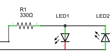
The 2 wires on the left of the diagram are each connected to a different digital pin on the Pico. Clearly, with 2 pins and 2 LEDs, this configuration offers no savings. It does, however, help to illustrate the central principle behind the way that charlieplexing works. For LED 1 to be lit, the top wire needs to be HIGH and the bottom wire LOW. This would mean that LED 2 would be receiving a LOW at its anode and a HIGH at its cathode - so it would not be lit. To light LED 2, the top wire needs to be LOW and the bottom HIGH. This means that LED 1 is turned off. Current only flows the correct way through one of the diodes. The resistor is always in series with the LED that is lit.
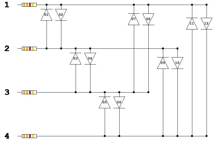
Adding another digital pin, makes the circuit below. The LEDs shown as plain diodes,
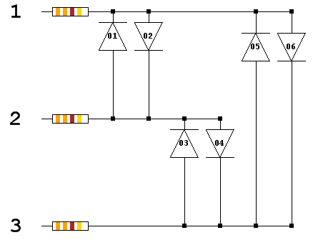
For this matrix, we need to use that third logic state, INPUT. To light LED 1, there needs to be a HIGH signal on wire 2 and a LOW signal on wire 1. Wire 3 needs to be disconnected in some fashion in order for that circuit to complete without lighting any of the other LEDs. This is done by setting the pin to an INPUT. This puts it into a high impedance state and effectively disconnects it from the circuit. In the high impedance state, the pin is neither high, nor low and little or no current is being passed to the circuit from it. The full truth table of pin settings for each LED are as follows,
| LED | Pin 1 | Pin 2 | Pin 3 |
|---|---|---|---|
| 1 | LOW | HIGH | INPUT |
| 2 | HIGH | LOW | INPUT |
| 3 | INPUT | HIGH | LOW |
| 4 | INPUT | LOW | HIGH |
| 5 | HIGH | INPUT | LOW |
| 6 | LOW | INPUT | HIGH |
In the schematic, the LEDs are shown in pairs. Each pair is connected to the same two pins. Pin 1 is connected to the cathode of LED 1 and the anode of LED 2, Pin 2 is connected to the anode of Pin 1 and the cathode of Pin 2. Pin 3 is not connected to this pair so needs to be disconnected to light one of these two LEDs. LEDs 3 & 4 and 5 & 6 also form pairs in this way.
By increasing the number of digital pins from 2 to 3, we were able to add an extra 4 LEDs. The scaling up of the system is what matters and how that compares to traditional multiplexing. When charlieplexing, the number of LEDs is equal to n x (n-1) where n is the number of pins. 4 pins can control 12 LEDs, 5 pins can control 20 LEDs and so on. If we used traditional multiplexing, we could use 16 pins to control an 8x8 LED matrix. The same number of pins using charlieplexing could control 240 LEDs.
Charlieplexing works wonderfully when you only need one of many LEDs to be on at a time. You can give the appearance of more than one LED being on if you switch quickly enough. This will have a dimming effect on the LEDs and, depending on how well you work your timing, may introduce a small amount of flicker to the circuit.
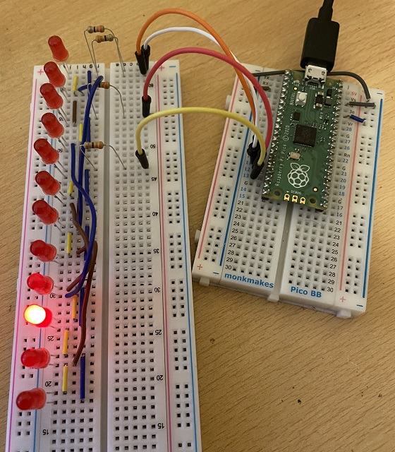
This is my test circuit based on the schematic for 6 charlieplexed LEDs. I have connected the 3 resistors to GP10, GP11 and GP12.
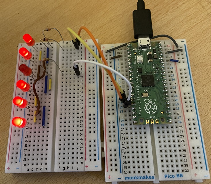
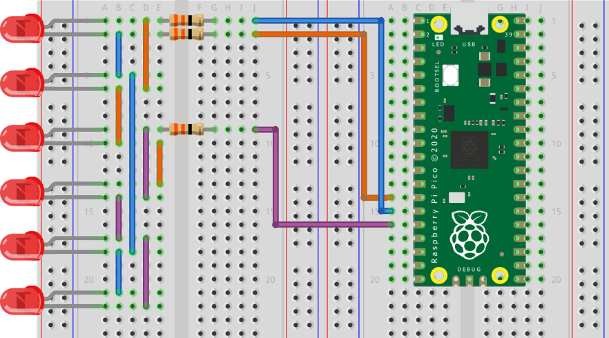
Having the LEDs in a straight line like this means that you need a few extra jumpers. It does make the circuit a little nicer though. The Fritzing shows the connections I used. I found it easier to make the circuit by following the schematic from left to right on each of the 3 rows.
This first program shows how to light up the LEDs one at a time,
from machine import Pin, Timer
from time import sleep

gp = [10,11,12]

patterns = [[1,0],
            [0,1],
            [2,1],
            [1,2],
            [2,0],
            [0,2]]

led = [Pin(i, Pin.IN) for i in gp]

def reset_pins():
    global led
    led = [Pin(i, Pin.IN) for i in gp]
    for i in led:
        i.value(0)

def set_pins(high, low):
    global led
    reset_pins()
    led[high] = Pin(gp[high], Pin.OUT)
    led[low] = Pin(gp[low], Pin.OUT)
    led[high].value(1)
    led[low].value(0)

def light_led(led_num):
    set_pins(patterns[led_num][0], patterns[led_num][1])

while True:
    for i in range(6):
        light_led(i)
        sleep(0.5)
Although this is not optimised for speed, particularly when changing the pin configurations. I thought I'd give it a go at having several LEDs on at a time. This program turns the 6 LEDs into a binary counter. The main while loop switches between the LEDs really quickly whilst the timer increments the number that is going to be represented.
from machine import Pin, Timer
from time import sleep , sleep_ms

gp = [10,11,12]

patterns = [[1,0],
            [0,1],
            [2,1],
            [1,2],
            [2,0],
            [0,2]]

led = [Pin(i, Pin.IN) for i in gp]

def reset_pins():
    global led
    led = [Pin(i, Pin.IN) for i in gp]
    for i in led:
        i.value(0)

def set_pins(high, low):
    global led
    reset_pins()
    led[high] = Pin(gp[high], Pin.OUT)
    led[low] = Pin(gp[low], Pin.OUT)
    led[high].value(1)
    led[low].value(0)

def light_led(led_num):
    set_pins(patterns[led_num][0], patterns[led_num][1])

def change_pattern(t):
    global pattern
    pattern = (pattern + 1) % 64

pattern = 0
tmr = Timer()
tmr.init(period = 250, mode = Timer.PERIODIC, callback = change_pattern)

while True:
    bits = [pattern >> i & 1 for i in range(6)]
    for i in range(6):
        if bits[i]:
            light_led(i)
        sleep_ms(1)
This wasn't perfect and there is some flicker. Some improvement could be had from only changing the configuration of pins that need it. Further improvements would need a different approach to the program beyond the scope of my experiments.
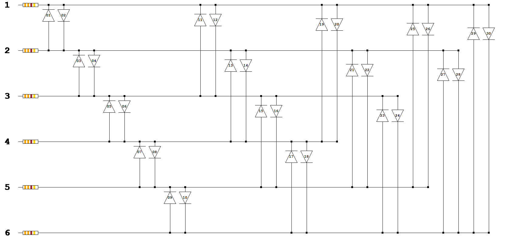
Having successfully wired up 6 LEDs, I thought I'd have a go at doing 12. This needed a larger breadboard and a little more patience. This is a schematic showing how the circuit scales up,
I find it a lot easier to follow these schematics than I do breadboard diagrams. I have also written a program that generates the schematics for different numbers of pins. This is why the LEDs are shown as simple diodes. Here is the circuit I made on a full size breadboard.
Here is the adapted program to light each LED in turn.
from machine import Pin, Timer
from time import sleep , sleep_ms

gp = [10,11,12,13]

patterns = [[1,0],
            [0,1],
            [2,1],
            [1,2],
            [3,2],
            [2,3],
            [2,0],
            [0,2],
            [3,1],
            [1,3],
            [3,0],
            [0,3]]

led = [Pin(i, Pin.IN) for i in gp]

def reset_pins():
    global led
    led = [Pin(i, Pin.IN) for i in gp]
    for i in led:
        i.value(0)

def set_pins(high, low):
    global led
    reset_pins()
    led[high] = Pin(gp[high], Pin.OUT)
    led[low] = Pin(gp[low], Pin.OUT)
    led[high].value(1)
    led[low].value(0)

def light_led(led_num):
    set_pins(patterns[led_num][0], patterns[led_num][1])

while True:
    for i in range(12):
        light_led(i)
        sleep(0.5)
Apart from adding the pin to the list, you need to change the patterns list to define which pins should be high and low to turn on each LED. That is easy to read from the schematic.
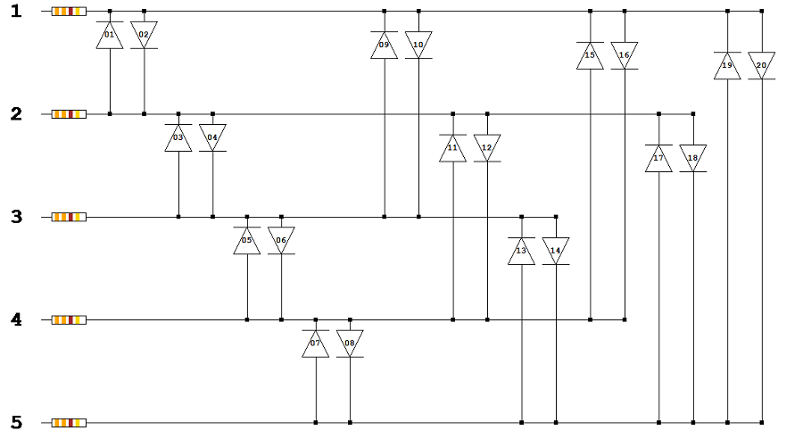
Here is the schematic for 5 pins and 20 LEDs. Although I have shown that, with some concentration, you can build these circuits on a breadboard, I was not keen to start building this one.
A few more schematics in case you are interested,
Charlieplexing Schematic - 6 pins, 30 LEDs
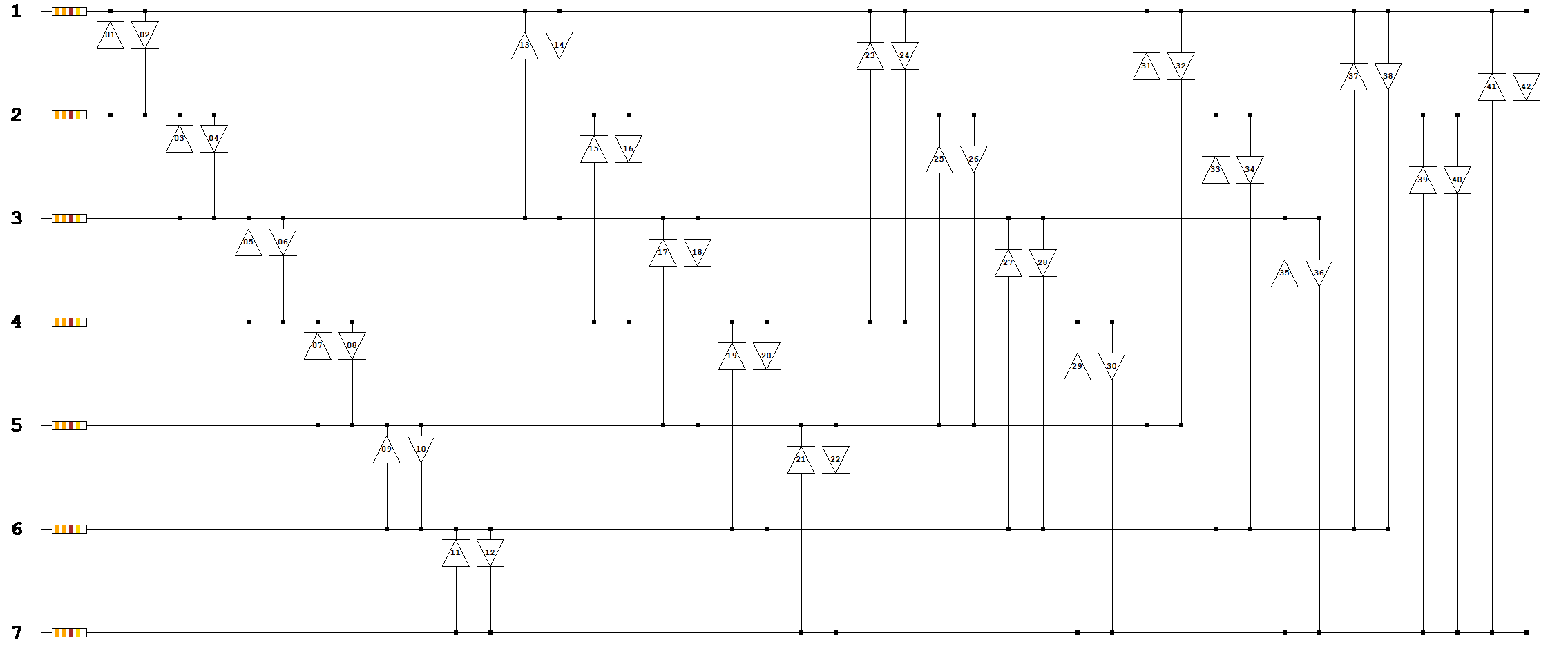
Charlieplexing Schematic - 7 pins, 42 LEDs
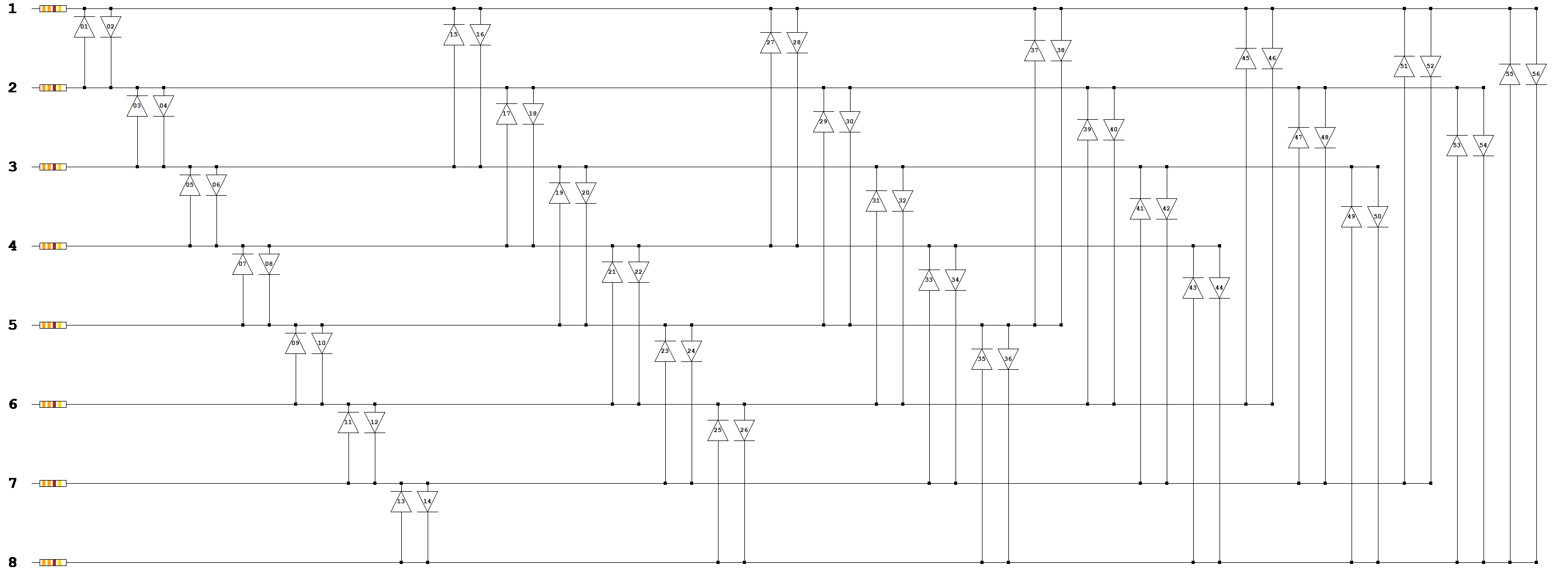
Charlieplexing Schematic - 8 pins, 56 LEDs