Raspberry Pi Pico
MicroPython - Basics
MicroPython - More Involved
MicroPython - Pico W
MicroPython - micro:bit
MicroPython - Projects
CircuitPython - Some Basics
CircuitPython - HID Adventures
CircuitPython - Experiments
Other Pages
![]()


Raspberry Pi Pico
Multiplexer 74HC4051
The 74HC4051 is an integrated circuit which acts as an 8-channel analog multiplexer/demultiplexer. For the examples on this page, I used a Sparkfun breakout board that cost me £2 and looks like this,
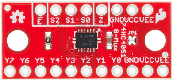
It takes 4 GPIO pins to read or write 8 independent signals. This means that you could have 8 LEDs connected to the board, 8 buttons, 8 single pin sensors, resistor ladders and more.
The pins marked S0, S1, S2 are used to select the pin you want to control. You write the digital values in the table to these pins to select the channel you want to use.
| Pin | S2 | S1 | S0 |
|---|---|---|---|
| Y0 | 0 | 0 | 0 |
| Y1 | 0 | 0 | 1 |
| Y2 | 0 | 1 | 0 |
| Y3 | 0 | 1 | 1 |
| Y4 | 1 | 0 | 0 |
| Y5 | 1 | 0 | 1 |
| Y6 | 1 | 1 | 0 |
| Y7 | 1 | 1 | 1 |
After that, it's a simple matter of reading or writing digital or analog values to the z pin on the board.
This IC isn't the same as a shift register. For a start, you are not limited to digital values and you can input and output on any of the 8 channels. The downside is that the signals you write only go to your devices when that particular pin is selected. Although you can connect LEDs, as in the example on this page, you have to work harder in your program to get the effects you tend to want from LEDs. Where your output signal is a trigger, that would work quite well.
Input, on the other hand, is quite handy. The board works pretty well for reading a bunch of buttons and analog sensors.
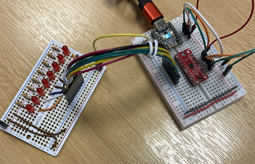
For my first circuit, I connected 8 LEDs to the outputs. Because I find myself often needing to connect 8 LEDs to a circuit with 330 Ohm resistors, I have soldered some proto-board and made a hookup cable to make this quicker to do. The perma-proto board is from Adafruit and is a really high quality product. In this photograph, I am using the Tiny 2040 to give me a little more space on the breadboard.
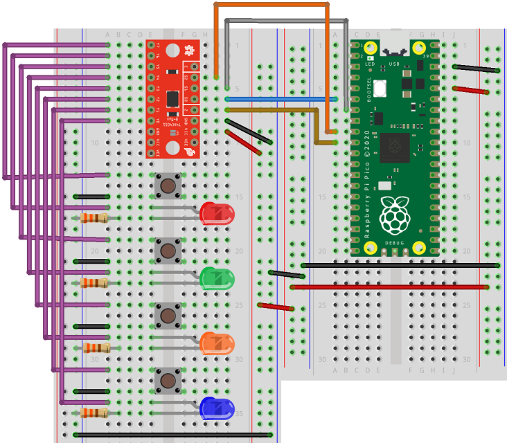
This is a Fritzing circuit showing the classic Pico. It is functionally equivalent to the one I made,
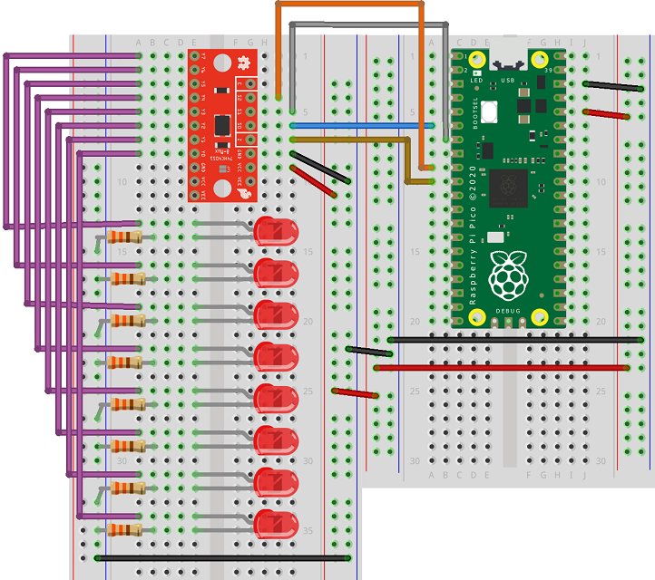
The anodes (long legs) of the LEDs are connected to the output pins on the multiplexer (Y0 - Y7). I have used GP4, GP5 and GP6 for the selection pins (S0-S2). The Z pin is the one that sets the signals for the components. I have used GP7 for that.
The following program blinks each LED on and off in turn. The select_pin subroutine makes sure that the signal on the Z pin goes to the correct output.
from machine import Pin
from time import sleep

select_pin_nums = [4,5,6]
s_pins = [Pin(i, Pin.OUT) for i in select_pin_nums]
z_pin = Pin(7, Pin.OUT)

def select_pin(p, pins):
    for i in range(3):
        pins[i].value((p>>i)&1)

while True:
    for i in range(8):
        select_pin(i, s_pins)
        z_pin.value(1)
        sleep(0.25)
        z_pin.value(0)
        sleep(0.25)
My next circuit is about inputs. I wired up 8 buttons with one pin on each button going to GND and the other one going to Y0-Y7. Again, I have a pre-soldered board with my 8 buttons on. This one hasn't been soldered as nicely as the LEDs but it still works well enough for test purposes.
This is the Fritzing equivalent of this circuit.
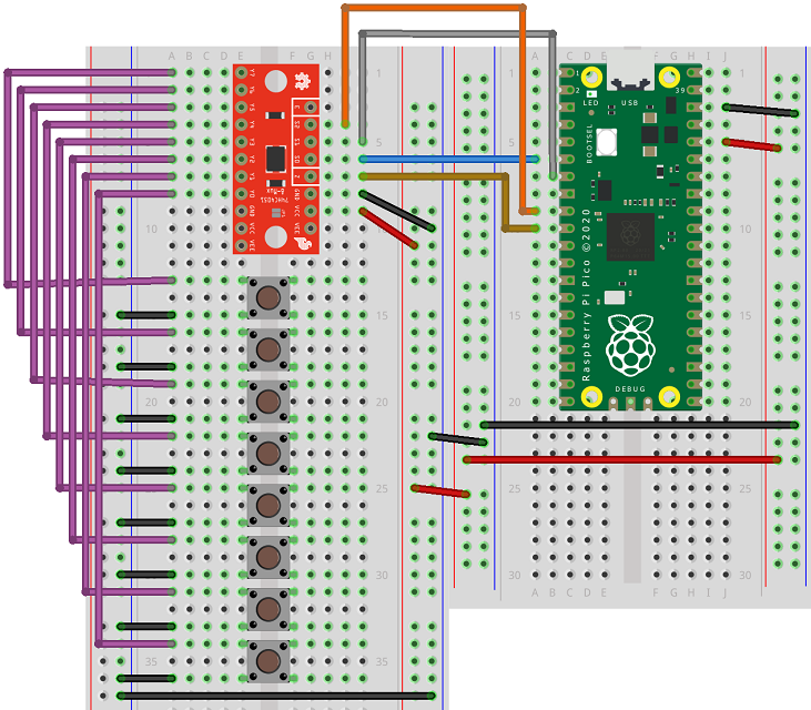
This program outputs a binary pattern showing which buttons are being held down.
from machine import Pin
from time import sleep

select_pin_nums = [4,5,6]
s_pins = [Pin(i, Pin.OUT) for i in select_pin_nums]
z_pin = Pin(7, Pin.IN, Pin.PULL_UP)

def select_pin(p, pins):
    for i in range(3):
        pins[i].value((p>>i)&1)

def read_buttons():
    btns = 0
    for i in range(8):
        select_pin(i, s_pins)
        btns += z_pin.value() << (i)
    return btns

last = 255

while True:
    b = read_buttons()
    if b != last:
        print('{:08b}'.format(b))
    last = b
    sleep(0.02)
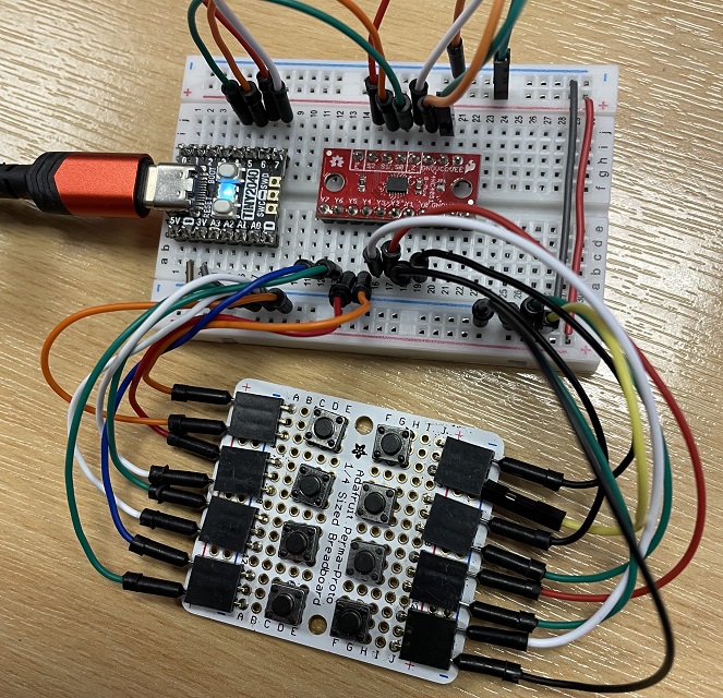
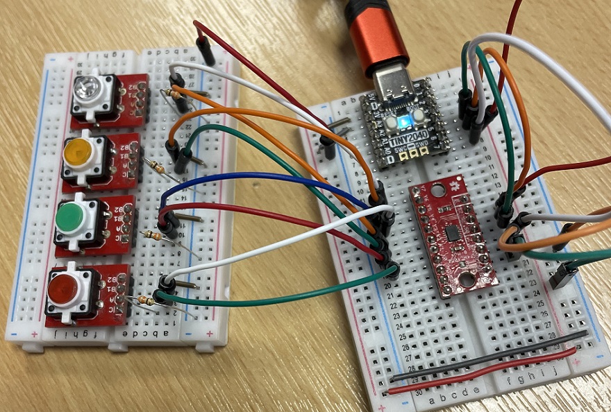
My next experiment involved mixing inputs and outputs. I wired up 4 buttons and 4 LEDs. I have some nice little breakouts with LED buttons (both components in the same package). You can also do this with separate components.
Here is the equivalent Fritzing diagram.
For this program, I wanted to have the LEDs light up when I pressed each button. In order to be able to have more than one LED on at a time, it is necessary to switch very quickly between each one. This works well for some of the LEDs. For some colours, you may need to think more carefully about the resistor you are using to make sure that there is equal brightness between them. I messed around a lot with the timing until I got something that looked reasonable.
from machine import Pin
from time import sleep

select_pin_nums = [4,5,6]
s_pins = [Pin(i, Pin.OUT) for i in select_pin_nums]
z_pin = Pin(7, Pin.OUT)

def select_pin(p, pins):
    for i in range(3):
        pins[i].value((p>>i)&1)

def read_buttons():
    z_pin = Pin(7, Pin.IN, Pin.PULL_UP)
    btns = 0
    for i in range(4,8):
        select_pin(i, s_pins)
        btns += z_pin.value() << (i-4)
    return btns

def light_leds(leds):
    z_pin = Pin(7, Pin.OUT)
    for i in range(4):
        select_pin(i, s_pins)
        if leds>>i & 1:
            z_pin.value(0)
        else:
            z_pin.value(1)
        sleep(0.005)

last = 15

while True:
    b = read_buttons()
    if b != last:
        print('{:04b}'.format(b))
    last = b
    light_leds(last)
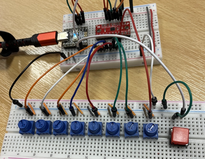
My last circuit is a little unusualy for anything other than experimental purposes. I wanted to see how well I could make the board work for analog devices. It turns out to be pretty easy. The only change you have to make is to use an ADC pin for the Z pin. I also added a button to my circuit so that I was only taking readings from the sensors when I pressed the button.
For this circuit, I changed the Z pin to GP26. I wired up a button to GP27. I wired the potentiometers as you see in the page in this section, the outer pins going to 3v3 and GND and the middle pin going to the Y0-Y7 pins.
Considering the circuit, the code ends up being surprising compact.
from machine import Pin, ADC
from time import sleep

select_pin_nums = [4,5,6]
s_pins = [Pin(i, Pin.OUT) for i in select_pin_nums]
z_pin = ADC(26)

btn_a = Pin(27,Pin.IN,Pin.PULL_UP)

def select_pin(p, pins):
    for i in range(3):
        pins[i].value((p>>i)&1)

def read_pots():
    pots = []
    for i in range(8):
        select_pin(i, s_pins)
        pots.append(z_pin.read_u16()//256)
    return pots

# subroutine to handle button presses
def btn_a_handler(pin):
    data = read_pots()
    print(data)

# attach IRQ to button pin
btn_a.irq(trigger=Pin.IRQ_RISING, handler=btn_a_handler)
Summary
This board is really good fun to experiment with. The basic arithmetic of the pin control tells you that you are using half the number of pins you would normally need for your circuit. I have done relatively straightforward things here with no complex protocols being enacted over the board, but I suppose you could do that. The pin saving is not so urgent on the Pico compared to some microcontrollers. Using the Tiny 2040 or similar, you might be able to take advantage of the small form factor of your main microcontroller and expand its capabilities.
The real benefit of this board is that the main business is being done on a single pin. That may not be so important for basic IO but does make a difference when we are talking about PWM or ADC. On the Pico, you have a limited number of ADCs. Using this board, you can have 8 devices using that single ADC.