Raspberry Pi Pico
MicroPython - Basics
MicroPython - More Involved
MicroPython - Pico W
MicroPython - micro:bit
MicroPython - Projects
CircuitPython - Some Basics
CircuitPython - HID Adventures
CircuitPython - Experiments
Other Pages
![]()


Raspberry Pi Pico
ANO Scroll Wheel Rotary Encoder
This page is a record of my first quick experiments with the ANO Directional Navigation and Scroll Wheel Rotary Encoder and Breakout board. Here it is on the edge of my test circuit. It is black so a little hard to photograph.
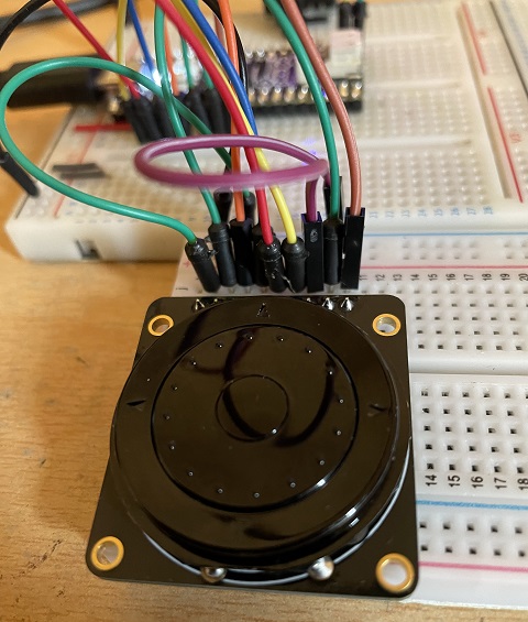
What you are seeing here is something that is a little like the scroll wheel on the original ipod. The circle of dots is the wheel part of the component. There are also 5 switches built in. The top, right, bottom and left points of the outer circle are push switches. The centre of the circle is also a switch. This gives a nice package of controls that can be used in your projects. The component is mounted on a breakout board that Adafruit make to make it easy to use.
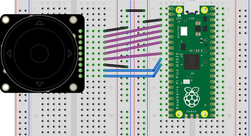
Here is a Fritzing diagram for the basic connections that I used.
The first thing I did with this is to do a simple test of the switches and the rotary encoder and do some output to the shell.
from machine import Pin
from time import sleep

# event handlers
def btn_press(pin):
    bs = ["L", "U", "R", "D", "M"]
    b = btns.index(pin)
    print(bs[b], "(" + str(b) + ")")

# left, up, right, down, middle
btn_pins = [2, 3, 4, 5, 6]
btns = [Pin(i, Pin.IN, Pin.PULL_UP) for i in btn_pins]

for i in btns:
    i.irq(trigger=Pin.IRQ_FALLING, handler=btn_press)

a = Pin(8, Pin.IN, Pin.PULL_UP)
b = Pin(7, Pin.IN, Pin.PULL_UP)

counter = 0
lasta = 1

print(counter)

while True:
    aread = a.value()
    bread = b.value()
    if not aread and lasta:
        if bread==1:
            counter += 1
        else:
            counter -= 1
        print(counter)
    lasta = aread
    sleep(0.01)
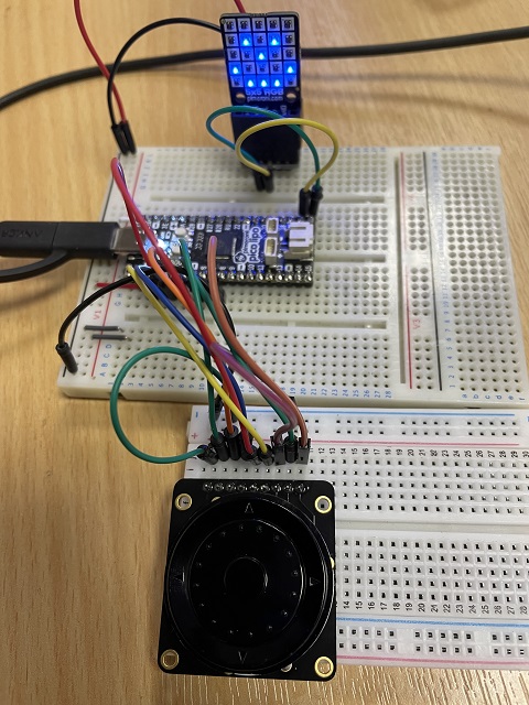
With that done, I added the 5x5 RGB LED breakout from Pimoroni to my circuit, connecting it to the i2c pins GP16 and GP17. I first wanted to see how easy it would be to use the directional buttons to move around a blinking cursor and the middle button to toggle an LED on and off. This would make it easy to design a 5x5 image for the display. This could obviously be done with 5 basic pushbuttons too.
Here is a photograph of the circuit.
For this program, I decided to return to polling the buttons. The interrupts work really well in some situations. For this application, though, I found that the polling worked much better.
from machine import Pin, I2C
from time import sleep
from scrollrgb import SCROLLRGB


# refresh display
def refresh():
    for yy in range(5):
        for xx in range(5):
            if pixel_data[yy][xx]:
                display.set_pixelxy(xx, yy, back[0], back[1], back[2])
            else:
                display.set_pixelxy(xx, yy, 0, 0, 0)
    display.show()

def blink(state):
    if state:
        display.set_pixelxy(x, y, cursor[0], cursor[1], cursor[2])
    else:
        if pixel_data[y][x]:
            display.set_pixelxy(x, y, back[0], back[1], back[2])
        else:
            display.set_pixelxy(x, y, 0, 0, 0)
    display.show()

def read_btns(btn_list):
    result = 0
    for i, b in enumerate(btn_list):
        result +=  (b.value()^1)<<i
    return result

def pressed(pattern, b):
    return pattern>>b & 1

# set up buttons
btn_pins = [2, 3, 4, 5, 6]
btns = [Pin(i, Pin.IN, Pin.PULL_UP) for i in btn_pins]

i2c=I2C(0,sda=Pin(16), scl=Pin(17))
display = SCROLLRGB(i2c)

x = y = 0
on = 1
back = [0, 0, 255]
cursor = [255, 0, 0]

pixel_data = [[0,0,0,0,0],[0,0,0,0,0],[0,0,0,0,0],[0,0,0,0,0],[0,0,0,0,0]]
refresh()

previous = 0
counter = 0

while True:
    if counter == 50:
        on = not on
        counter = 0
        blink(on)
    reading = read_btns(btns)
    if reading != previous:
        blink(0)
        if pressed(reading, 3):
            y += 1
        elif pressed(reading, 2):
            x += 1
        elif pressed(reading, 1):
            y -= 1
        elif pressed(reading, 0):
            x -= 1
        elif pressed(reading, 4):
            # toggle pixel
            pixel_data[y][x] = not pixel_data[y][x]
        x = max(0, min(x, 4))
        y = max(0, min(y, 4))
    counter += 1
    previous = reading
    sleep(0.01)
For the last circuit, I tried to add the rotary encoder as a method of controlling the dot. This works, after a fashion, alongside the button pressing method from the previous circuit. It's not quite there, though, in my view.
from machine import Pin, I2C
from time import sleep
from scrollrgb import SCROLLRGB


# refresh display
def refresh():
    for yy in range(5):
        for xx in range(5):
            if pixel_data[yy][xx]:
                display.set_pixelxy(xx, yy, back[0], back[1], back[2])
            else:
                display.set_pixelxy(xx, yy, 0, 0, 0)
    display.show()

def blink(state):
    if state:
        display.set_pixelxy(x, y, cursor[0], cursor[1], cursor[2])
    else:
        if pixel_data[y][x]:
            display.set_pixelxy(x, y, back[0], back[1], back[2])
        else:
            display.set_pixelxy(x, y, 0, 0, 0)
    display.show()

def read_btns(btn_list):
    result = 0
    for i, b in enumerate(btn_list):
        result +=  (b.value()^1)<<i
    return result

def pressed(pattern, b):
    return pattern>>b & 1

# set up buttons

btn_pins = [2, 3, 4, 5, 6]
btns = [Pin(i, Pin.IN, Pin.PULL_UP) for i in btn_pins]

# rotary encoder
a = Pin(8, Pin.IN, Pin.PULL_UP)
b = Pin(7, Pin.IN, Pin.PULL_UP)

i2c=I2C(0,sda=Pin(16), scl=Pin(17))
display = SCROLLRGB(i2c)

x = y = 0
on = 1
back = [0, 0, 255]
cursor = [255, 0, 0]

pixel_data = [[0,0,0,0,0],[0,0,0,0,0],[0,0,0,0,0],[0,0,0,0,0],[0,0,0,0,0]]
refresh()

previous = 0
counter = 0

lasta = 1

while True:
    aread = a.value()
    bread = b.value()
    if counter == 50:
        on = not on
        counter = 0
        blink(on)
    reading = read_btns(btns)
    if reading != previous:
        blink(0)
        if pressed(reading, 3):
            y += 1
        elif pressed(reading, 2):
            x += 1
        elif pressed(reading, 1):
            y -= 1
        elif pressed(reading, 0):
            x -= 1
        elif pressed(reading, 4):
            # toggle pixel
            pixel_data[y][x] = not pixel_data[y][x]
        x = max(0, min(x, 4))
        y = max(0, min(y, 4))
    elif not aread and lasta:
        blink(0)
        n = x + y * 5
        if bread==1:
            n += 1
        else:
            n -= 1
        n = max(0, min(n, 24))
        x = n % 5
        y = n // 5
    lasta = aread
    counter += 1
    previous = reading
    sleep(0.01)
All in all, I am delighted with this component. Getting the component and the breakout is going to cost you around £10. It isn't the cheapest but is nice and compact and really high quality. It is going to work well in a finished project that isn't going to be dismantled soon after making. It's also a quick and easy way to build a test circuit where you need directional control. I will find myself using this for some other projects fairly soon.